This simple electronic dice is an ideal starter project to introduce youngsters
and those still young at heart to the dark arts of microcontrollers and circuit
building. We take you step by step through the process. For your troubles
you will build a useful electronic dice. It will put an end to you scrabbling
around under the table to retrieve a dice that’s been carelessly tossed and
also an end to cheating… It landed on a six! It really did… yeah right.
By Florian Schäffer (Germany)
This simple electronic dice is an ideal starter project to introduce youngsters and those still young at heart to the dark arts of microcontrollers and circuit building. We take you step by step through the process. For your troubles you will build a useful electronic dice. It will put an end to you scrabbling around under the table to retrieve a dice that’s been carelessly tossed and also an end to cheating… It landed on a six! It really did… yeah right.
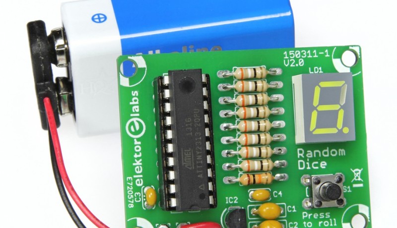
This simple circuit simulates the rolling of a dice (or ‘die’ to pedants). When the roll button is pressed the display shows random numbers in the range of one to six, after a while the display settles with one number on the LED display. Don't miss any project, take out a free membership to Elektor.POST now!
To make the project easier to build for beginners we have ruled out the use of any SMD components and used leaded components throughout.
The dice circuit
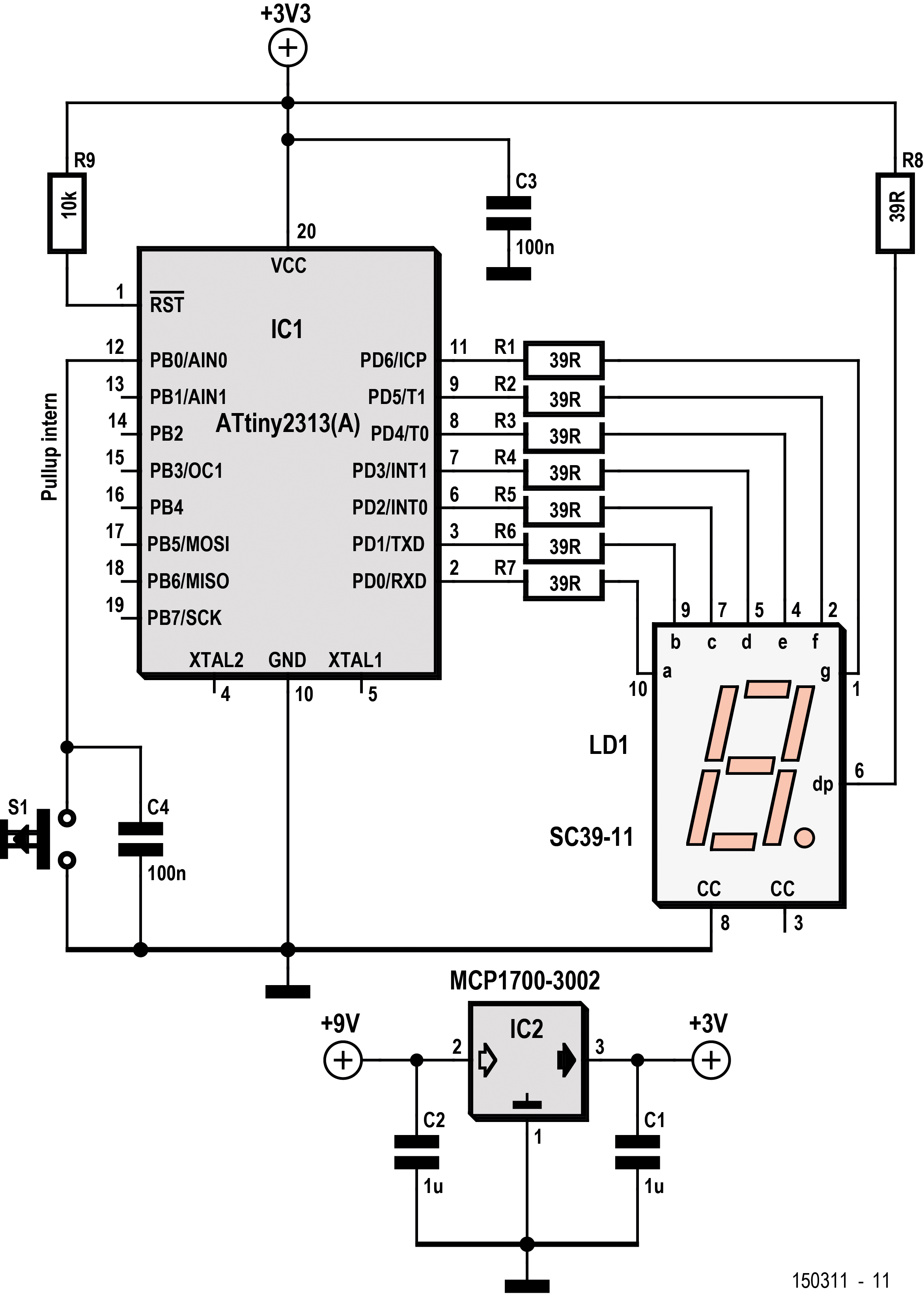
The circuit in Figure 1 shows the connections between the pushbutton, the seven-segment display and the Atmel microcontroller I/O pins. Resistors R1 to R8 are required to limit the current flowing to each of the LED display segments. IC2 is a simple regulator which converts the 9 V battery voltage to a stable 3 V for the circuit. C4 is used to suppress the signal produced by contact bounce from pushbutton S1. This button is used to start the dice rolling. When the circuit has not been used for a while the display is turned off to reduce power consumption and promote longer battery life. The decimal point LED is used to indicate that the circuit is on.
Figure 1. The circuit using an Atmel microcontroller looks… dicey.
Read full article
Hide full article
Add a rating to this article
★★★★★
★★★★★
Page 1 / 5
Login
No account yet?Register for free!
Forgot password?
Please enter your email address. Instructions for resetting the password will be emailed to you now.

Discussion (0 comments)