
4 Channel Remote control by XBEE [150408]
433 MHz radios are great for making remote control toys and RC switches which are based on throwing some switches on and off here and there and running a couple of motors. But for greater degree of freedom, say running a few servos for controlling the rudder, elevator, aileron for direction and the brushless motor for propeller action at the same time feedback from each of these action , the 433 MHz radio control comes to a grinding halt.
Xbee:
433 MHz radios are great for making remote control toys and RC switches which are based on throwing some switches on and off here and there and running a couple of motors. But for greater degree of controls say running a few servos for controlling the rudder, elevator, aileron for direction and the brushless motor for propeller action at the same time feedback from each of these action , the 433 mhz radio control comes to a grinding halt.
The above situation calls for a special kinds of radios and xbees are just that. Xbees are small 2.4 GHZ transceivers with a small micro controller on board. The xbee is the communication protocol which is used in many other instruments too.
There are two type of xbee radio transceivers – series-1 & series-2. Each series has two varieties again - normal and pro. While the normal has a range of 30 to 40 meters in indoor / urban situations , along the line of sight it works upto 100 to 125 meters depending upon series-1 & series-2 respectively. The pro works upto 1.6 km on line of sight. However with yagi directional antenna Xbee pro can reach as long as 20 km on line of sight.
While series-1 has 8 digital I/O pins the series-2 has 11 pins. The series-2 is more advanced and can be made into a mesh networks where the range can be extended to any length by putting router xbees in between.
Types of Xbee:
Each xbee is associated with an antenna built on the hardware itself. There are several types of antenna – simple wire, U.FL type, RPSMA and Chip type.
[Figure-1]
[Figure-2]
The size of each hardware is hardly little bigger than a 1 Rupee coin. The pro is little bigger and consume more power while transmitting..
The simple wire antenna is enough to get you going with all sorts of xbee experiments. The xbee need to be programmed before putting into our desired use.
Programming an Xbee:
For programming an xbee, put it into an explorer / break out board and then connect it to the computer usb port. There are serial port explorer board also available for connecting it to the serial port of your computer.
Several communication programs are available for programming an xbee like procontrol, xterm, pcu, x-ctu even putty but among all , x-ctu is the easiest, windows based , graphical and of course takes longest time. But once you master in x-ctu you can quickly connect xbee to any other communication program and do the reprogramming of your xbee by short AT commands.
Cost: The cost of xbee series-2 is about Rs:1200 from the mail delivery shops in India and the cost of series-2 Pro is Rs:2200 approximately. The USB explorer board costs about Rs:500.
Our Project: We air aiming for developing a 4 channel wireless controller with feedback. One Xbee at each end and a Arduino nano micro controller for interfacing and running the servo controls. The normal 4 channel controller available in the market runs on 9 to 12 volts and does not have any feed back therefore you don't know whether the remote receiver has acted or not.
However, most of these controllers are used in the remote controlled toys like – RC planes, RC cars, RC ships etc. Seeing their movements you can know well before feed back whether it has accepted the command or not but for long range missions the feed back comes very handy.
For delivering analog inputs like joystick movements we have 4 pins and for digital commands we have another 7 pins. So literally we can extend our controller to 11 channel wireless remote controller.
Here in our case we will use 4 analog channel for delivering 4 analog inputs and one
digital channel for a combined feed back.
Get-set-go: Download x-ctu from ….. and install it on an windows PC. Position the Xbee on the explorer board and then connect it with the USB port of your PC. Fire up x-ctu and see whether it has detected the device or not. Normally it detects serial port 18 to 20 on USB for the first Xbee explorer board.
[Figure-3]
Configuring the Xbee:
Few things you have to take care to make two xbees to talk to each other freely and precisely and all these can be done very easily in X-CTU software. The X-CTU has 4 tabbed windows – PC-settings , Range test , Modem & Configuration. In the PC settings window there are 3 sub windows located at the bottom – Host setup, User com ports, Network Interface. In case you have not found your right com ports you can press the 'Network Interface' and press the 'Digi Device Discovery' and you're sure to find your device now – good job done !
Now press the 'Test / Query' button on the right side of the same 'PC Settings' window and see what Xbee it discovers. Checkbox the 'enable API' because we will use that feature in the Coordinator Xbee. Now come to the 'Configuration' window where most of the settings need to be accomplished by you.
In the Configuration window press the 'Read' button and your screen will be washed with an awe full amount of data. Don't get afraid because you need to configure only a few parameters.
Click on the 'Always update firmware' as this will keep the Xbee updated with the latest softwares. In the 'Function Set' pull down menu select the 'Xbee coordinator API' . In the 'Version' pull down select the highest number. Now in the ‘Networking’ parameters window find the 'PAN' parameter. PAN stands for Personal-Area-Network and give it a 4 byte number – say 1234. Hey, don't give 1234 because everybody does it and in case one more crank hot head guy is experimenting with xbee in your area you both will collide in the air space for bandwidth. Give it a decent 7821 and it will be OK for now.
In fact to communicate between two Xbees one to be made Coordinator and the other to be made Router and here we're preparing the Coordinator Xbee.
Come to the 'Addressing' parameter at 'DH' & 'DL' . They are called the 'High' and 'LOW' address. DH is a 32 bit address written on the side of the Xbee itself. Enter this parameter here. In most cases it's the same number for all generic Xbees – 0013A200 (find out yours for sure..). Just below this number you will find another 32 bit number inscribed on each Xbees . This is the DL number.
The DL parameter is to be switched between the Coordinator & the Router – The Routers number to be entered into the Coordinator and vice versa. After doing that now press 'Write' and the setup will be written in your Coordinator Xbee. See the message below. You may need your Internet connection on now. When it is over the 'finished' message will appear on the bottom.
You have set up the Xbee Coordinator successfully. Now remove the Coordinator and insert the other Xbee and open the 'Configuration' window. After pressing the 'Read' button and getting the parameters shown on the middle window go to the 'Function Set' pull down menu and select 'Xbee Router' . In the 'Version' pull down select the highest number. Find the PAN in the ‘Networking’ parameter and enter 7821 (same as the Coordinator Xbee). Set the JV parameter ‘1’ as it will set the Router to rejoin the coordinator on startup.
In the ‘Addressing’ parameter the DH shall be as per written on the Xbee and the DL shall be the DL number written on the Coordinator Xbee. So far so good. Now come down further to 'IO Settings' to setup the analog & digital data entry part of the router Xbee.
In the ‘IO Setting’ parameter part. D0,D1,D2,D3 – these are four analog input pins through which we will send our four channel analog data. By default these pins are disabled. To make them enable go to the 'IO Settings' and make D0, D1,D2,D3 as 2 (as analog data entry) . However, these pins can be made as Digital data input or output also by simply changing it to 3 , 4 or 5. Set D5 to 4. This pin will be used as feedback signal from the receiver Xbee.
Now we come to the ‘I/O Sampling’ section. Set the IR sampling to 64. i.e 0X64 , Once on 100 milli sec the feed back will be checked.
Now press ‘Write’ and let the configuration be written in the stupid brain of Xbee.
------ ------- -------- -------
Relax now, the major part i.e the Xbee configuration is over. We will do some programming here and our Remote will be up and running. But before that lets understand how the Xbee reads the analog input data.
Analog input & Xbee:
The Xbee analog input pins read 0 volt to 1.2 volt maximum. Any voltage above 1.2 will be treated as maximum or '1' . since most Xbees operate at 3.3 volt we will reduce this voltage to 1.2 volt level by adding a suitable resistor along the input device.
Suppose the analog sensor is an LDR whose impedance varies from 0 to 10K so to have the 3.3 voltage dropped to 1.2 voltage across the LDR we put a 20K resistor in series with the LDR so that the 2/3 voltage (of 3.3 volt) will be dropped before reaching the LDR.
[Figure-4]
In our case we will use 3 nos 10K pots to send analog readings to control the Radar, Aileron and Elevator of an RC plane with a direct feed back from the Receiver. R2=10 K and R1=2*10 = 20K to have the 1.2 Volt across R2.
Transmitter Design:
Well, that's the schematic of the 4 channel Tx based on Xbee. Each 10K pot will control one aspect of the RC plane. 3.3 volt supply is taken from a Li-Ion cell of 3.7 volt.
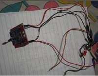
And here's the practical view of my prototype before putting into a box. Only one Pot is shown in the picture. The Xbee is used on a breakout board for ease of use but they can be used without breakout board / explorer board also.
[Figure-9]
[Figure-6]
Here goes the receiver built on Xbee connected to Arduino Nano, 3 servo controller for controlling three aspects of the RC plane and a brush less motor for propeller control. The 3.3 Volt power supply for the Xbee is taken from the Nano board and the Nano is back feed from the brushless motor battery of 11.1 volt. The Xbee is used on a breakout board but later while actual flying it will be used without breakout / explorer board because on board the weight is a major concern.
The ESC for the brushless motor is connected to the digital pin no 12 on Nano, the servo controller of Radar, Aleron & Elevators are connected to Digital pin 9,10 11 of Nano.
Here's a block diagram of the entire receiver model:
Only 4 wires have been taken out from the Xbee (3.3v, gnd, Tx & Rx). Consult the pin diagram of Xbee for detail pin locations. While the 3.3 volt wire goes to the 3.3 volt pin of the nano the ground wire (black wire) goes to the ground pin of the Nano. The Tx & Rx wire goes to the Rx & Tx pin of the Nano respectively.
The + wire (red wire) of the servos are connected together to the +5 volt pin of the Nano while all the ground wires (black wires) of the Servos are connected together and goes to the ground pin of the Nano. Since only one or two servos will be operating together at a time. Therefore, the small amount of power will be drawn from the Nano board itself without considering for a separate 5 volt power source for the servos.
[Figure-7]
[Figure-8]
While starting the brushless motor, the pot connected to the pin no:12 is turned slowly in one direction. At one point the motor will start rotating. Hold the position for a while after that turn it further to achieve the highest speed.
The Radar, the Aileron and the elevator will be controlled by the rods / strings pulled by the servos. Arduino Nano is used for simplicity and small form factor.
The Arduino Sketch:
[Appeared in EFY, India in 2014]
433 MHz radios are great for making remote control toys and RC switches which are based on throwing some switches on and off here and there and running a couple of motors. But for greater degree of controls say running a few servos for controlling the rudder, elevator, aileron for direction and the brushless motor for propeller action at the same time feedback from each of these action , the 433 mhz radio control comes to a grinding halt.
The above situation calls for a special kinds of radios and xbees are just that. Xbees are small 2.4 GHZ transceivers with a small micro controller on board. The xbee is the communication protocol which is used in many other instruments too.
There are two type of xbee radio transceivers – series-1 & series-2. Each series has two varieties again - normal and pro. While the normal has a range of 30 to 40 meters in indoor / urban situations , along the line of sight it works upto 100 to 125 meters depending upon series-1 & series-2 respectively. The pro works upto 1.6 km on line of sight. However with yagi directional antenna Xbee pro can reach as long as 20 km on line of sight.
While series-1 has 8 digital I/O pins the series-2 has 11 pins. The series-2 is more advanced and can be made into a mesh networks where the range can be extended to any length by putting router xbees in between.
Types of Xbee:
Each xbee is associated with an antenna built on the hardware itself. There are several types of antenna – simple wire, U.FL type, RPSMA and Chip type.
[Figure-1]
[Figure-2]
The size of each hardware is hardly little bigger than a 1 Rupee coin. The pro is little bigger and consume more power while transmitting..
The simple wire antenna is enough to get you going with all sorts of xbee experiments. The xbee need to be programmed before putting into our desired use.
Programming an Xbee:
For programming an xbee, put it into an explorer / break out board and then connect it to the computer usb port. There are serial port explorer board also available for connecting it to the serial port of your computer.
Several communication programs are available for programming an xbee like procontrol, xterm, pcu, x-ctu even putty but among all , x-ctu is the easiest, windows based , graphical and of course takes longest time. But once you master in x-ctu you can quickly connect xbee to any other communication program and do the reprogramming of your xbee by short AT commands.
Cost: The cost of xbee series-2 is about Rs:1200 from the mail delivery shops in India and the cost of series-2 Pro is Rs:2200 approximately. The USB explorer board costs about Rs:500.
Our Project: We air aiming for developing a 4 channel wireless controller with feedback. One Xbee at each end and a Arduino nano micro controller for interfacing and running the servo controls. The normal 4 channel controller available in the market runs on 9 to 12 volts and does not have any feed back therefore you don't know whether the remote receiver has acted or not.
However, most of these controllers are used in the remote controlled toys like – RC planes, RC cars, RC ships etc. Seeing their movements you can know well before feed back whether it has accepted the command or not but for long range missions the feed back comes very handy.
For delivering analog inputs like joystick movements we have 4 pins and for digital commands we have another 7 pins. So literally we can extend our controller to 11 channel wireless remote controller.
Here in our case we will use 4 analog channel for delivering 4 analog inputs and one
digital channel for a combined feed back.
Get-set-go: Download x-ctu from ….. and install it on an windows PC. Position the Xbee on the explorer board and then connect it with the USB port of your PC. Fire up x-ctu and see whether it has detected the device or not. Normally it detects serial port 18 to 20 on USB for the first Xbee explorer board.
[Figure-3]
Configuring the Xbee:
Few things you have to take care to make two xbees to talk to each other freely and precisely and all these can be done very easily in X-CTU software. The X-CTU has 4 tabbed windows – PC-settings , Range test , Modem & Configuration. In the PC settings window there are 3 sub windows located at the bottom – Host setup, User com ports, Network Interface. In case you have not found your right com ports you can press the 'Network Interface' and press the 'Digi Device Discovery' and you're sure to find your device now – good job done !
Now press the 'Test / Query' button on the right side of the same 'PC Settings' window and see what Xbee it discovers. Checkbox the 'enable API' because we will use that feature in the Coordinator Xbee. Now come to the 'Configuration' window where most of the settings need to be accomplished by you.
In the Configuration window press the 'Read' button and your screen will be washed with an awe full amount of data. Don't get afraid because you need to configure only a few parameters.
Click on the 'Always update firmware' as this will keep the Xbee updated with the latest softwares. In the 'Function Set' pull down menu select the 'Xbee coordinator API' . In the 'Version' pull down select the highest number. Now in the ‘Networking’ parameters window find the 'PAN' parameter. PAN stands for Personal-Area-Network and give it a 4 byte number – say 1234. Hey, don't give 1234 because everybody does it and in case one more crank hot head guy is experimenting with xbee in your area you both will collide in the air space for bandwidth. Give it a decent 7821 and it will be OK for now.
In fact to communicate between two Xbees one to be made Coordinator and the other to be made Router and here we're preparing the Coordinator Xbee.
Come to the 'Addressing' parameter at 'DH' & 'DL' . They are called the 'High' and 'LOW' address. DH is a 32 bit address written on the side of the Xbee itself. Enter this parameter here. In most cases it's the same number for all generic Xbees – 0013A200 (find out yours for sure..). Just below this number you will find another 32 bit number inscribed on each Xbees . This is the DL number.
The DL parameter is to be switched between the Coordinator & the Router – The Routers number to be entered into the Coordinator and vice versa. After doing that now press 'Write' and the setup will be written in your Coordinator Xbee. See the message below. You may need your Internet connection on now. When it is over the 'finished' message will appear on the bottom.
You have set up the Xbee Coordinator successfully. Now remove the Coordinator and insert the other Xbee and open the 'Configuration' window. After pressing the 'Read' button and getting the parameters shown on the middle window go to the 'Function Set' pull down menu and select 'Xbee Router' . In the 'Version' pull down select the highest number. Find the PAN in the ‘Networking’ parameter and enter 7821 (same as the Coordinator Xbee). Set the JV parameter ‘1’ as it will set the Router to rejoin the coordinator on startup.
In the ‘Addressing’ parameter the DH shall be as per written on the Xbee and the DL shall be the DL number written on the Coordinator Xbee. So far so good. Now come down further to 'IO Settings' to setup the analog & digital data entry part of the router Xbee.
In the ‘IO Setting’ parameter part. D0,D1,D2,D3 – these are four analog input pins through which we will send our four channel analog data. By default these pins are disabled. To make them enable go to the 'IO Settings' and make D0, D1,D2,D3 as 2 (as analog data entry) . However, these pins can be made as Digital data input or output also by simply changing it to 3 , 4 or 5. Set D5 to 4. This pin will be used as feedback signal from the receiver Xbee.
Now we come to the ‘I/O Sampling’ section. Set the IR sampling to 64. i.e 0X64 , Once on 100 milli sec the feed back will be checked.
Now press ‘Write’ and let the configuration be written in the stupid brain of Xbee.
------ ------- -------- -------
Relax now, the major part i.e the Xbee configuration is over. We will do some programming here and our Remote will be up and running. But before that lets understand how the Xbee reads the analog input data.
Analog input & Xbee:
The Xbee analog input pins read 0 volt to 1.2 volt maximum. Any voltage above 1.2 will be treated as maximum or '1' . since most Xbees operate at 3.3 volt we will reduce this voltage to 1.2 volt level by adding a suitable resistor along the input device.
Suppose the analog sensor is an LDR whose impedance varies from 0 to 10K so to have the 3.3 voltage dropped to 1.2 voltage across the LDR we put a 20K resistor in series with the LDR so that the 2/3 voltage (of 3.3 volt) will be dropped before reaching the LDR.
[Figure-4]
In our case we will use 3 nos 10K pots to send analog readings to control the Radar, Aileron and Elevator of an RC plane with a direct feed back from the Receiver. R2=10 K and R1=2*10 = 20K to have the 1.2 Volt across R2.
Transmitter Design:
Well, that's the schematic of the 4 channel Tx based on Xbee. Each 10K pot will control one aspect of the RC plane. 3.3 volt supply is taken from a Li-Ion cell of 3.7 volt.
And here's the practical view of my prototype before putting into a box. Only one Pot is shown in the picture. The Xbee is used on a breakout board for ease of use but they can be used without breakout board / explorer board also.
[Figure-9]
[Figure-6]
Here goes the receiver built on Xbee connected to Arduino Nano, 3 servo controller for controlling three aspects of the RC plane and a brush less motor for propeller control. The 3.3 Volt power supply for the Xbee is taken from the Nano board and the Nano is back feed from the brushless motor battery of 11.1 volt. The Xbee is used on a breakout board but later while actual flying it will be used without breakout / explorer board because on board the weight is a major concern.
The ESC for the brushless motor is connected to the digital pin no 12 on Nano, the servo controller of Radar, Aleron & Elevators are connected to Digital pin 9,10 11 of Nano.
Here's a block diagram of the entire receiver model:
Only 4 wires have been taken out from the Xbee (3.3v, gnd, Tx & Rx). Consult the pin diagram of Xbee for detail pin locations. While the 3.3 volt wire goes to the 3.3 volt pin of the nano the ground wire (black wire) goes to the ground pin of the Nano. The Tx & Rx wire goes to the Rx & Tx pin of the Nano respectively.
The + wire (red wire) of the servos are connected together to the +5 volt pin of the Nano while all the ground wires (black wires) of the Servos are connected together and goes to the ground pin of the Nano. Since only one or two servos will be operating together at a time. Therefore, the small amount of power will be drawn from the Nano board itself without considering for a separate 5 volt power source for the servos.
[Figure-7]
[Figure-8]
While starting the brushless motor, the pot connected to the pin no:12 is turned slowly in one direction. At one point the motor will start rotating. Hold the position for a while after that turn it further to achieve the highest speed.
The Radar, the Aileron and the elevator will be controlled by the rods / strings pulled by the servos. Arduino Nano is used for simplicity and small form factor.
The Arduino Sketch:
#include "softwareserial.h"
#include "servo.h"

int ri = false; // keeps track of the desired remote // on/off state
int lastri = false; // record of prior remote state
unsigned long lastsent = 0;
int val1 =0;
int val2 =0;
int val3 =0;
int val4 =0;

Servo myservo1;
Servo myservo2;
Servo myservo3;
Servo myservo4;

void setup()
{
  myservo1.attach(12); //Propeller
  myservo2.attach(11); //Radar
  myservo3.attach(10); // Aeleron
  myservo4.attach(9); // Elevator

  Serial.begin(9600);
  pinMode(13, OUTPUT);
}

void loop()
{
  if(Serial.available() >=29)
  {
    if(Serial.read() == 0x7E)
    {
      for(int i=0;i<20;i++)
      {
        Serial.read();
      }

      int h1=0;
      int l1=0;
      int l2=0;
      int h2=0;
      int l3=0;
      int h3=0;
      int l4=0;
      int h4=0;

      h1 = Serial.read();
      l1 = Serial.read();
      h2 = Serial.read();
      l2 = Serial.read();
      h3 = Serial.read();
      l3 = Serial.read();
      h4 = Serial.read();
      l4 = Serial.read();

      val1 = l1 + 256 * h1;
      val2 = l2 + 256 * h2;
      val3 = l3 + 256 * h3;
      val4 = l4 + 256 * h4;
      int x1 = map(val1,0,1023,0,180);
      int x2 = map(val2,0,1023,0,180);
      int x3 = map(val3,0,1023,0,180);
      int x4 = map(val4,0,1023,0,180);


      /*
      Serial.print(val1);
      Serial.print("-----");
      Serial.print(val2);
      Serial.print("-----");
      Serial.print(val3);
      Serial.print("-----");
      Serial.print(val4);
      Serial.print("-----");
      Serial.println("End of data");
      */


      myservo1.write(x1);
      myservo2.write(x2);
      myservo3.write(x3);
      myservo4.write(x4);
      delay(10);
    }
  }

  if (val1 > 0 && val1 <= 50)
  {
    //Extend the feedback for val2, val3 and val4 also
    digitalWrite(13, LOW);
    ri = false;
  }

  if (val1 > 50 && val1 <= 1050)
  {
    digitalWrite(13, HIGH);
    ri = true;
  }

  if (val1 > 1050 && val1 <= 1023)
  {
    digitalWrite(13, LOW);
    ri = false;
  }
  // set the indicator immediately when there's a state change
  if (ri != lastri)
  {
    if (ri==false) setRemoteState(0x4);
    if (ri==true)
    {
      setRemoteState(0x5);
    }
    lastri = ri;
  }
  if (millis() - lastsent > 100 )
  {
    if (ri==false) setRemoteState(0x4);
    if (ri==true)
    {
      setRemoteState(0x5);
    }
    lastsent = millis();
  }
}

void setRemoteState(int value)
{ // pass either a 0x4 or 0x5 to turn the pin on/off
  Serial.print(0x7E, BYTE); // start byte
  Serial.print(0x0, BYTE); // high part of length (always zero)
  Serial.print(0x10, BYTE); // low part of length (the number of bytes
  // that follow, not including checksum)
  Serial.print(0x17, BYTE); // 0x17 is a remote AT command
  Serial.print(0x0, BYTE); // frame id set to zero for no reply
  // ID of recipient, or use 0xFFFF for broadcast
  Serial.print(00, BYTE);

  Serial.print(00, BYTE);
  Serial.print(00, BYTE);
  Serial.print(00, BYTE);
  Serial.print(00, BYTE);
  Serial.print(00, BYTE);
  Serial.print(0xFF, BYTE); // 0xFF for broadcast
  Serial.print(0xFF, BYTE); // 0xFF for broadcast
  // 16 bit of recipient or 0xFFFE if unknown
  Serial.print(0xFF, BYTE);
  Serial.print(0xFE, BYTE);
  Serial.print(0x02, BYTE); // 0x02 to apply changes immediately on remote
  // command name in ASCII characters
  Serial.print('D', BYTE);
  Serial.print('5', BYTE);
  // command data in as many bytes as needed
  Serial.print(value, BYTE);
  // checksum is all bytes after length bytes
  long sum = 0x17 + 0xFF + 0xFF + 0xFF + 0xFE + 0x02 + 'D' + '5' + value;
  Serial.print( 0xFF - ( sum & 0xFF) , BYTE ); // calculate the proper checksum
  delay(10); // safety pause to avoid overwhelming the
  // serial port (if this function is not implemented properly)
}
[Appeared in EFY, India in 2014]
Discussion (2 comments)