
How-To Calculate the Prospective Short-Circuit Current or PSCC
on
Before we go any further, let's make clear that this article covers electrical engineering, not electronics. So, when a 'circuit' is mentioned here, it refers to an electrical supply circuit connecting lamps, switches, power outlets, and machines, including all wiring.
What is the PSCC?
The prospective short-circuit current or PSCC is the maximum current that can flow through a shorted electrical circuit. It is also known as 'available fault current' or 'short-circuit making current', and, as with any current, it conforms to Ohm’s Law. Therefore, the circuit’s supply voltage and its impedance together determine the PSCC value we crave to know.
Why would I want to know the PSCC?
To select devices like circuit breakers and fuses that will effectively protect an electrical installation, you need the PSCC value. Such protective devices must be able to sustain the PSCC to provide a reliable protection. If the breaking capacity or interrupting rating of the protective device is too low, the PSCC may destroy it or cause an electric arc (Figure 1). In either case, the breaking device may not operate correctly, and dangerous situations may arise.

What about the trip current?
The breaking capacity of a circuit breaker is not the same thing as its trip current. The latter is the maximum current a circuit breaker 'considers' safe to pass; the breaking current on the other hand is the current the device can withstand without getting damaged. For instance, the type SN201 L C32-L 1+N pole miniature circuit breaker (MCB) from ABB has a rated trip current (In) of 32 A and a rated short-circuit current (Icn) of 4.5 kA (at 230 / 400 VAC). This is because the short-circuit current depends on the capacity of the power source and is unrelated to the current drawn by the load protected by the circuit breaker.
Measuring the PSCC
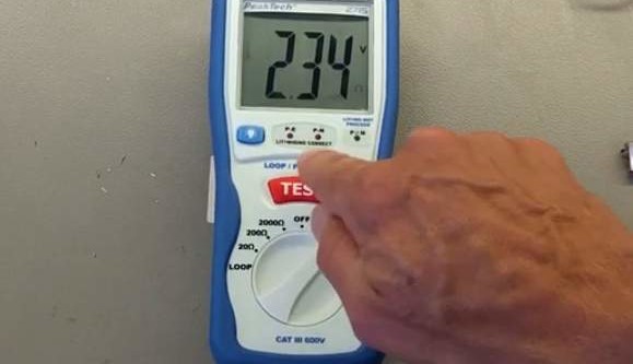
You can measure the PSCC of an electrical installation with a PSC Tester. This is an easy-to-operate instrument that calculates the PSCC value of a circuit in ampères (A) and kiloampères (kA). Although pressing the 'Test' button is usually enough to obtain a value, connecting the instrument properly to the system requires knowledge of what you are trying to measure.
Generally, a PSCC test is conducted at the distribution board between phase (P) and neutral (N). In the case of a power outlet using the moulded test cable supplied with the tester, the test is done between the Phase and Protective Earth (PE; E) conductors. Before pressing the 'Test' button, make sure the tester indicates that it is safe to do so.
What does a PSC tester do?
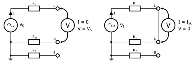
A PSC tester first measures the open-circuit voltage at the terminals (VS, see Figure 2). Then it applies a small load for a short time to make a current of a known value flow through the circuit (IT, Figure 3). With the test current flowing, the instrument again measures the voltage V at the terminals. Due to the impedance (ZLN) of the circuit, V will be a bit lower than VS. That impedance is expessed as
ZLN = (VS - V) / IT [Ω]
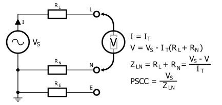
By assuming ZLN to be constant, the tester calculates the PSCC as: VS / ZLN.
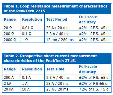
The value of the test current depends on the selected measurement range and goes from, say, 2 A, up to 25 A or more. The duration of the measurement also varies with the range and is usually in the order of a few tens of milliseconds. see Table 1 and Table 2 for some real-world data from a real PSC Tester.
What is Loop Testing?
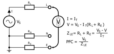
PSC testers can also measure the Earth fault loop impedance ZS or ZE or the prospective fault current PFC (also known as PEFC). This corresponds to the impedance of the circuit between the P and the (P)E conductors in the event of a short between the two (Figure 4). A low impedance will result in a high fault current, making a protective device trip quickly. It also helps to ensure a small potential difference between the (P)E conductor at the outlet and the earth you are standing on.
When measured at a power outlet, the Earth fault loop impedance is called ZS. When taken at the supply’s entry point, it is called ZE. As such:
ZS = ZE + RL + RE [Ω]
with RL and RE the respective impedances of the P and (P)E conductors between the supply entry point and the outlet.
Note that even with a small test current a residual current device (RCD) may trip when it is sensitive or when there is leakage in the circuit under test. To avoid this from happening you may want to bypass the RCD temporarily (do not forget to restore its connections when done!).
Calculate the PFC
The Earth fault loop impedance is measured in the same way as the PSCC, but again depending on the selected range, the test current can be much smaller (as low as tens of milliamperes). Also, take the measurement between the phase and the earth conductors instead of between phase and neutral. The P(E)FC is obtained by calculating VS / ZLE.
Notes
Depending on the wiring it can happen that the PSCC and P(E)FC values differ. If this is the case, use the highest value of the two for specifying a circuit breaker.
Working on live electrical installations can kill you. We warned you.

Want more great Elektor content like this?
Then Take out an Elektor membership today and never miss an article, project, or tutorial.
Discussion (0 comments)