
Free Back Article: DDS Function Generator
January 10, 2020
on
on
Original publication: Elektor magazine 5/2015, page 68.
Author: Theodorou Gerasimos (Greece)
Free download expires: Friday 17 January 2020.
Note: Since its publication of the project in 2015, components, software elements, webpages and other elements mentioned in the article may be subject to updating to the present day.
PCB available: yes, see Products below.
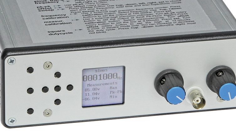
• Direct Digital Synthesis (DDS) with analogue front-end
• Frequency range: 1 – 10 MHz
• Frequency resolution: 0.28 Hz
• Output: 0 – 15 Vpp
• THD+N (100 kΩ load, B > 500 kHz):
-- 1 V, 1 kHz: 0.12% (0.09% for B = 22 kHz)
-- 5 V, 1 kHz: 0.1% (0.09% for B = 22 kHz)
-- 1 V, 10 kHz: 0.1% (0.09% for B = 80 kHz)
-- 5 V, 10 kHz: 0.09% (0.08% for B = 80 kHz)
-- 1 V, 100 kHz: 0.1%
-- 5 V, 100 kHz: 0.08%
• S/N (referred to 1 V): 72 dB
• Maximum output (10 MΩ load):
-- Sine: 16 Vpp
-- Triangle: 16 Vpp
-- Square: 18 Vpp
• DC offset voltage range: –10 to +10 V
• Output impedance: 50 Ω
• Duty cycle (square wave): 1 – 99%
• Rise and fall time (80%, square wave): 100 ns
• Sweep mode
• Power consumption: 3 VA


Like what you’re seeing? Then go to the article page and download a pdf copy of the full, original article. Downloading is free from Friday 10 January to Friday 17 January, 2020.
Author: Theodorou Gerasimos (Greece)
Free download expires: Friday 17 January 2020.
Note: Since its publication of the project in 2015, components, software elements, webpages and other elements mentioned in the article may be subject to updating to the present day.
PCB available: yes, see Products below.
Introduction
DDS chips are readily available, greatly simplifying the design of the analog part of a wide-range function- or signal generator. All you need to do (they say!) is choose one, add some suitable output circuitry, pick a microcontroller, provide a user interface and start programming. To which we reply: sweet dreams, here is the real story: power to the AD9834!
Specifications
• Direct Digital Synthesis (DDS) with analogue front-end• Frequency range: 1 – 10 MHz
• Frequency resolution: 0.28 Hz
• Output: 0 – 15 Vpp
• THD+N (100 kΩ load, B > 500 kHz):
-- 1 V, 1 kHz: 0.12% (0.09% for B = 22 kHz)
-- 5 V, 1 kHz: 0.1% (0.09% for B = 22 kHz)
-- 1 V, 10 kHz: 0.1% (0.09% for B = 80 kHz)
-- 5 V, 10 kHz: 0.09% (0.08% for B = 80 kHz)
-- 1 V, 100 kHz: 0.1%
-- 5 V, 100 kHz: 0.08%
• S/N (referred to 1 V): 72 dB
• Maximum output (10 MΩ load):
-- Sine: 16 Vpp
-- Triangle: 16 Vpp
-- Square: 18 Vpp
• DC offset voltage range: –10 to +10 V
• Output impedance: 50 Ω
• Duty cycle (square wave): 1 – 99%
• Rise and fall time (80%, square wave): 100 ns
• Sweep mode
• Power consumption: 3 VA
Selected Images
Like what you’re seeing? Then go to the article page and download a pdf copy of the full, original article. Downloading is free from Friday 10 January to Friday 17 January, 2020.
Read full article
Hide full article
Discussion (0 comments)