Many LEDs, those highly popular Light Emitting Diodes, die prematurely because they are improperly used by people who know little to nothing about electronics. Let's try to stop the massacre.
An LED or Light Emitting Diode is an electronic component that produces light when a current flows through it. Highly popular, LEDs are used by many people who know little to nothing about electronics. Part of them ignore that connecting an LED directly to a voltage source like a battery may well destroy the device; others vaguely know that there always seems to be a resistor in series with an LED but haven't a clue why.
Exploiting this lack of knowledge, people on the Internet sell 5-volt, 9-volt and 12-volt “LED resistors”. This may sound handy to those who don’t want to dig deeper but is a waste of money when you know that there ain’t such thing as a 12-volt LED resistor.
How to calculate an LED current limiting resistor.
Calculate the "LED resistor"
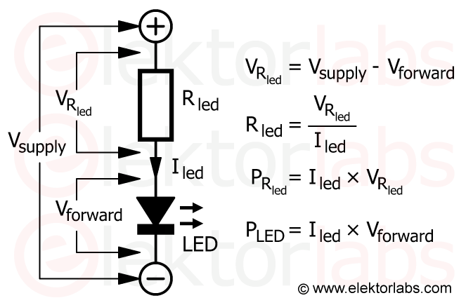
The resistor in question is a current limiting resistor and it prevents damaging the LED by excessive current. Its value depends on the supply voltage and the desired current through the LED. You can easily calculate the resistor value yourself:
Choose the LED’s supply voltage, call it Vsupply.
Choose the intensity of the current you want to push through the LED, Iled. The more current through an LED, the brighter it will shine. For common 3-mm and 5-mm LEDs 10 mA is a popular value.
Figure out the forward voltage (Vforward) of the LED for the current you chose. This voltage increases slightly with the intensity of the current and the wavelength of the emitted light (color of the LED). For a red LED it is often given as around 1.8 volts, but it depends on the LED. When dealing with red, orange, yellow and green LEDs, you can start by assuming a forward voltage of 2 V, blue and white LEDs have a value of around 3.2 V.
Now comes the magic. Say you want to power a green LED from a 9-volt battery, and make it pass a current of 15 mA (which is 0.015 A). Ohm’s law will now give you the resistor value:
(note that the units used are ohms, volts and ampères, not milliampères or something else). The nearest standard value is 470 Ω (±5%).
Checking this on a breadboard with a real, randomly chosen green LED from the junkbox and a resistor measured at 468 Ω, Vforward turned out to be 2.16 V (2.06 V for a red LED, and 2.04 V for a yellow one). Reversing the calculation, we find:
Pretty good, huh? If your LED current turns out to be too far from the desired value, adjust the resistor’s value. A smaller value increases the current, make it larger to decrease it.
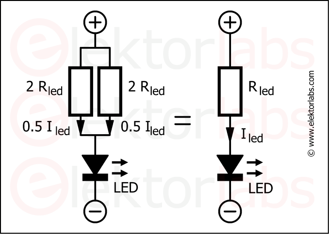
Two equal resistors in parallel share the power dissipation equally.
Heat is the enemy of electronics
The current that flows through the LED also flows through the series resistor. Current flowing through a resistor heats it up. The resistor must be capable of dissipating the heat without cracking up. In other words, it must be rated for the power it has to handle. The power dissipated by the resistor is now given as:
PR [W] = Iled [A] × VRled [V]
Thus, for our example, the resistance must be rated for:
0.015 × 7 = 0.105 W = 105 mW
This is fine for a standard 0.25 W through-hole carbon resistor, but too much for many thick-film SMD resistors. To solve this, you can place several identical resistors in parallel while multiplying their value by the number of resistors in parallel. For instance, one 470 Ω resistor can be replaced by two 940 Ω resistors in parallel. (In real life you would use two resistors of 1 kΩ.)
That's not all
Part 2 deepens the subject matter by explaining how to calculate LED power dissipation and more. Read on...
Read full article
Hide full article
Add a rating to this article
★★★★★
★★★★★
Page 1 / 1
Login
No account yet?Register for free!
Forgot password?
Please enter your email address. Instructions for resetting the password will be emailed to you now.


Discussion (0 comments)