
My Journey into the Cloud (10): The Pretzel Board
July 28, 2016
on
on
Regular readers of this sequel will already know that for my first attempts to remotely control a desk lamp I used a PC as a relay station configured as a MQTT client to receive text-based commands and forward them to a microcontroller board via the USB port.
From this basic configuration the next stage was to take the PC out of the equation and get the MQTT client running on the controller board itself. In the previous installment we experimented with a minimal library and discovered how simple the coding is to publish basic MQTT messages.
What’s still missing in the setup is a microcontroller system that can send and receive TCP / IP messages. A popular choice in many WiFi projects is the ESP8266 chip; it is relatively easy to use and controlled via a serial interface using text-based ‘AT’ command lines.
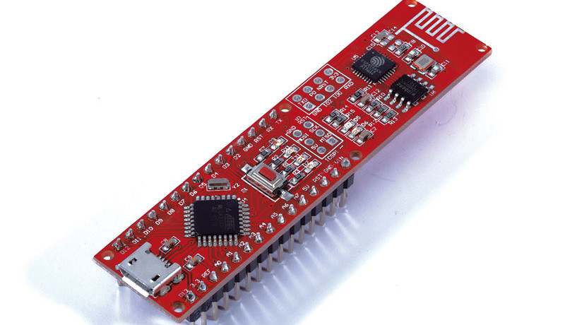
In order to get to know this chip a little better I searched for a simple development board and chose the Maker Kit IoT from Fabian Kainka, which is also available from the Elektor shop. The main component in the kit is the so-called Pretzel board; it contains an ESP8266 together with an ATmega328 controller pre-programmed with the Arduino bootloader. The ESP8266 UART interface connects to two pins of the ATmega328. The AVR controller’s hardware UART is assigned for use with the USB port so a software UART is needed to talk to the ESP8266. A small circuit on the board takes care of voltage level conversion.
For initial experiments, you just need to download the Arduino development environment and hook up the Pretzel board to the PC using a USB cable. Although I wouldn’t consider myself a complete devotee of the Arduino IDE and its libraries I decided to take this route initially to get everything up and running as soon as possible (the on-board controller can also be programmed using an ISP but you will need to solder a 2 x 3-way header in place).
I started out with the first program example given in the printed manual. With this program uploaded (select ‘Arduino Nano’ as the board type) the controller simply passes all characters that come in via USB directly to the ESP8266, and vice versa. This allows you to communicate using a terminal program on the PC directly to the ESP8266 on the Pretzel board.
I fired up my favorite terminal program ‘HTerm’; first I tried connecting the boards with my local WiFi network (Section 1.1). The AT commands are quite intuitive and I was quickly able to log in to my home office network without problems.
Then I started trying to use TCP / IP. I skipped the rest of Chapter 1 and Chapter 2 (UDP) and went to the first example in Chapter 3. Here we behave as a web browser and receive HTML code from the website www.example.com using the HTTP GET command.
For this next stage I wanted to send characters within my intranet. I used my own previously configured MQTT client with the TCP server extension to receive and display messages. A click on ‘TCP Listen’ received requests from the TCP client (ESP8266).
Using the command lines:
AT + CIPSTART = "TCP", "192.168.0.15", 80
AT + CIPSEND = 3
I was able to configure the ESP8266 chip to start the connection and then with the next line to send the payload data (plus the CR and LF characters appended to the text string automatically by the terminal program).
After entering and sending the characters using the terminal program they popped up in the TCP server’s receive window. Unfortunately the ESP8266 terminated the connection shortly afterwards. It was not yet possible for my TCP server to maintain the link. I had to shut it down, restart and click on ‘TCP Listen’ again. Can’t complain though, for a first attempt it was successful; and in the next episode you will get to find out how things progressed!
From this basic configuration the next stage was to take the PC out of the equation and get the MQTT client running on the controller board itself. In the previous installment we experimented with a minimal library and discovered how simple the coding is to publish basic MQTT messages.
What’s still missing in the setup is a microcontroller system that can send and receive TCP / IP messages. A popular choice in many WiFi projects is the ESP8266 chip; it is relatively easy to use and controlled via a serial interface using text-based ‘AT’ command lines.
In order to get to know this chip a little better I searched for a simple development board and chose the Maker Kit IoT from Fabian Kainka, which is also available from the Elektor shop. The main component in the kit is the so-called Pretzel board; it contains an ESP8266 together with an ATmega328 controller pre-programmed with the Arduino bootloader. The ESP8266 UART interface connects to two pins of the ATmega328. The AVR controller’s hardware UART is assigned for use with the USB port so a software UART is needed to talk to the ESP8266. A small circuit on the board takes care of voltage level conversion.
For initial experiments, you just need to download the Arduino development environment and hook up the Pretzel board to the PC using a USB cable. Although I wouldn’t consider myself a complete devotee of the Arduino IDE and its libraries I decided to take this route initially to get everything up and running as soon as possible (the on-board controller can also be programmed using an ISP but you will need to solder a 2 x 3-way header in place).
I started out with the first program example given in the printed manual. With this program uploaded (select ‘Arduino Nano’ as the board type) the controller simply passes all characters that come in via USB directly to the ESP8266, and vice versa. This allows you to communicate using a terminal program on the PC directly to the ESP8266 on the Pretzel board.
I fired up my favorite terminal program ‘HTerm’; first I tried connecting the boards with my local WiFi network (Section 1.1). The AT commands are quite intuitive and I was quickly able to log in to my home office network without problems.
Then I started trying to use TCP / IP. I skipped the rest of Chapter 1 and Chapter 2 (UDP) and went to the first example in Chapter 3. Here we behave as a web browser and receive HTML code from the website www.example.com using the HTTP GET command.
For this next stage I wanted to send characters within my intranet. I used my own previously configured MQTT client with the TCP server extension to receive and display messages. A click on ‘TCP Listen’ received requests from the TCP client (ESP8266).
Using the command lines:
AT + CIPSTART = "TCP", "192.168.0.15", 80
AT + CIPSEND = 3
I was able to configure the ESP8266 chip to start the connection and then with the next line to send the payload data (plus the CR and LF characters appended to the text string automatically by the terminal program).
After entering and sending the characters using the terminal program they popped up in the TCP server’s receive window. Unfortunately the ESP8266 terminated the connection shortly afterwards. It was not yet possible for my TCP server to maintain the link. I had to shut it down, restart and click on ‘TCP Listen’ again. Can’t complain though, for a first attempt it was successful; and in the next episode you will get to find out how things progressed!
Read full article
Hide full article
Discussion (0 comments)