
My Journey into the Cloud (20): The ESP32 creates its own Wi-Fi network
November 15, 2017
on
on
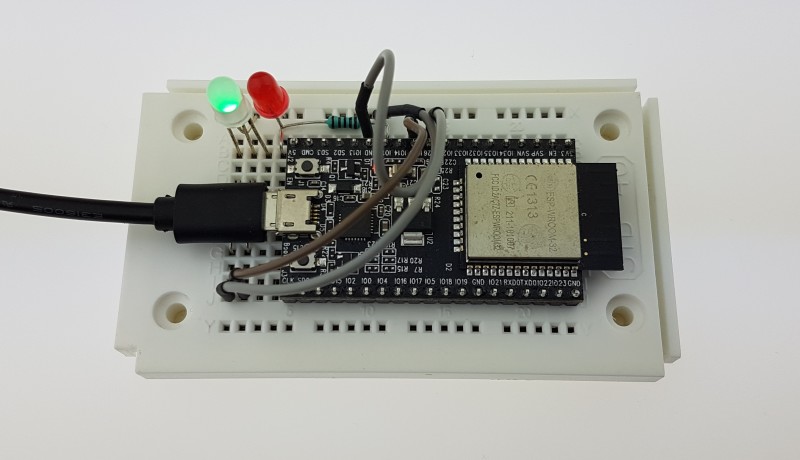
In the last episode of this series we produced a small web server using the ESP32 DevKitC. On request from a web browser, the ESP32 sends an HTML page containing several text boxes for the user to enter values. A subsequent click on the "Submit" button causes the web browser to start another HTTP request, where the values entered in the text fields are encoded into the URL (the expression in the browser address bar). The embedded web server evaluates the URL within the request, initiates a corresponding action and in turn sends a web page back to the browser. As a small demo, I used the values "00" or "FF" in the first text box field to turn a red LED on the board off and on. The values in all three text boxes are also stored in a small string-array. In principle, we could define and send several more configuration values to our small device via the web page - think of access data for a Cloud-portal.
The whole setup demonstrates how a web browser running on a smartphone or PC can serve as a user interface for an IoT device on the same network but there are still a couple of snags to iron out. Firstly the network configuration credentials are not stored in non-volatile memory so after a controller reset you need to reenter these values again. Secondly, it is not possible to configure the Wi-Fi network credentials (SSID and password) in this way because we can only configure after the ESP32 board is registered in the home network. Frustratingly, in all the previous installments we've had to write these configuration credentials for the network in the Arduino sketch then recompile the program and upload it - when you want to use a different network, this procedure needs to be repeated.
There is also a solution for the other problem mentioned above: The ESP32 has non-volatile storage (NVS) capability provided by an external flash card. This can be used to permanently store the configuration values. To make access really convenient, the developers at Espressif have written the ‘Preferences’ Library.
To try it out, I came up with a simple demo app again; all the hardware stays the same as in the last installment. After the first upload of the program, the ESP32 does not yet know the configuration credentials for the router network. In the setup function, it will still try to log into the network as in the previous installments, but of course fails. As a result, the RGB LED turns red. In the code the ESP32 is configured with:
as an Access Point mode+ Station mode and with:
the name of the access point is defined. This function parameter is the SSID of the self-generated network which can be found by just doing a Wi-Fi search.
If you log in with the PC here and enter "192.168.4.1" in the browser address field, then instead of the normal web page for controlling the LED, an HTML ‘Config’ page is served which allows you to enter the credentials such as the SSID (second text box) and the password (third text box) of the router network. For testing, the first text box can also be used to switch the red LED off and on by entering ‘00’ or ‘FF’.
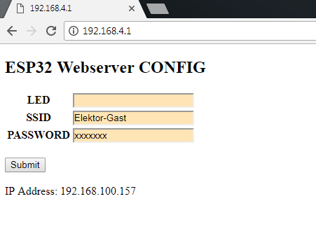
Once the page is sent, the HTTP request is evaluated by the Arduino sketch. The SSID and the password are stored in the NVS, so they will be available again if the power goes down. In addition, the ESP32 immediately tries to log into the router network using the configuration credentials that were sent. If successful the RGB LED lights up yellow briefly and then green (if the access data is not valid, the sequence is yellow briefly then red). The ESP32 now presents the configuration web page again but now displays its IP address on the home Wi-Fi network (see screenshot). Preferably you can try this out with a device other than the PC, for example a smartphone (because the PC is currently logged into the ESP32 network). Enter the address shown above in a browser and you will get the ESP32 web page where you will be able to switch the red LED as usual.
After a reset, the controller restarts with the setup function. If the network credentials stored in the NVS are correct, the RBG LED will turn green after a few seconds. Otherwise, however, the program sequence remains the same - in the network created by the ESP32, its configuration web page can be found again using a browser via the address ‘192.168.4.1’.
Both websites use the same array containing the configuration values (see previous installment). The normal webpage which controls the LEDs uses only the first value, whereas the configuration webpage uses the first three values, this is just to simplify the coding. It would take a bit more effort to improve the code by writing some separate functions to compile both web pages and to process the acknowledgements.
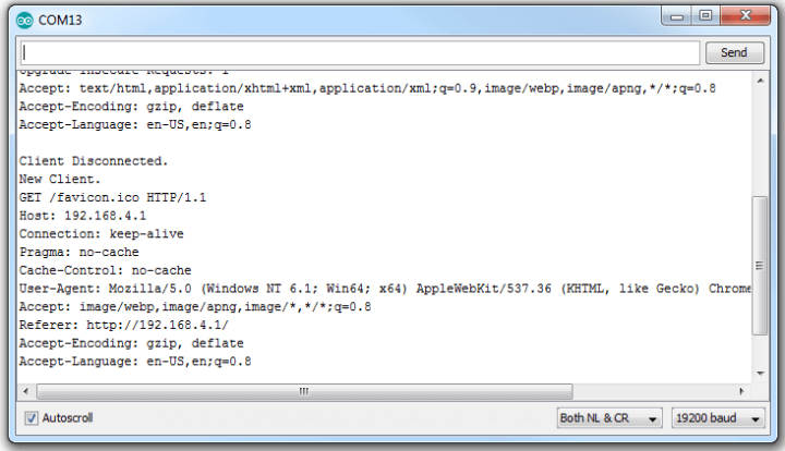
In order for the web server to decide which type of request is entered, the HTTP request is evaluated to find the address entered into the browser. In the HTTP request that comes from the browser to the ESP32 the address is usually located in the line ‘Host: ...’. The HTTP request can be viewed in the serial monitor as shown in the last episode:
To make the program easier to understand, I once again decided not to abstract everything so there is still a lot to do. In the next episodes we need to re-visit the cloud!
The whole setup demonstrates how a web browser running on a smartphone or PC can serve as a user interface for an IoT device on the same network but there are still a couple of snags to iron out. Firstly the network configuration credentials are not stored in non-volatile memory so after a controller reset you need to reenter these values again. Secondly, it is not possible to configure the Wi-Fi network credentials (SSID and password) in this way because we can only configure after the ESP32 board is registered in the home network. Frustratingly, in all the previous installments we've had to write these configuration credentials for the network in the Arduino sketch then recompile the program and upload it - when you want to use a different network, this procedure needs to be repeated.
The ESP32 as an Access Point
A handy feature of the ESP32 (and its little brother, the ESP8266) is that it can operate in ‘Access Point’ mode where it creates its own Wi-Fi network. This mode even works in parallel to its function as a ‘Station’ in a different router-based network (i.e. the mode we have used so far). A PC or Smartphone can log into the ESP32-generated network (by default a password does not need to be defined). The ESP32 exists in its own network and can be accessed via a web browser using the network address ‘192.168.4.1’ entered in the browser’s address field. The controller now serves an HTML page into which the user can enter the configuration credentials for the home router network (SSID, password). After it receives this information the ESP32 will log in to the router and connect to the Internet.There is also a solution for the other problem mentioned above: The ESP32 has non-volatile storage (NVS) capability provided by an external flash card. This can be used to permanently store the configuration values. To make access really convenient, the developers at Espressif have written the ‘Preferences’ Library.
To try it out, I came up with a simple demo app again; all the hardware stays the same as in the last installment. After the first upload of the program, the ESP32 does not yet know the configuration credentials for the router network. In the setup function, it will still try to log into the network as in the previous installments, but of course fails. As a result, the RGB LED turns red. In the code the ESP32 is configured with:
WiFi.mode(WIFI_AP_STA);
as an Access Point mode+ Station mode and with:
WiFi.softAP("ESP32_MyJourneyIoT");
the name of the access point is defined. This function parameter is the SSID of the self-generated network which can be found by just doing a Wi-Fi search.
If you log in with the PC here and enter "192.168.4.1" in the browser address field, then instead of the normal web page for controlling the LED, an HTML ‘Config’ page is served which allows you to enter the credentials such as the SSID (second text box) and the password (third text box) of the router network. For testing, the first text box can also be used to switch the red LED off and on by entering ‘00’ or ‘FF’.
Once the page is sent, the HTTP request is evaluated by the Arduino sketch. The SSID and the password are stored in the NVS, so they will be available again if the power goes down. In addition, the ESP32 immediately tries to log into the router network using the configuration credentials that were sent. If successful the RGB LED lights up yellow briefly and then green (if the access data is not valid, the sequence is yellow briefly then red). The ESP32 now presents the configuration web page again but now displays its IP address on the home Wi-Fi network (see screenshot). Preferably you can try this out with a device other than the PC, for example a smartphone (because the PC is currently logged into the ESP32 network). Enter the address shown above in a browser and you will get the ESP32 web page where you will be able to switch the red LED as usual.
After a reset, the controller restarts with the setup function. If the network credentials stored in the NVS are correct, the RBG LED will turn green after a few seconds. Otherwise, however, the program sequence remains the same - in the network created by the ESP32, its configuration web page can be found again using a browser via the address ‘192.168.4.1’.
The Wi-Fi library
The Arduino sketch included in the download for this article is ready for use straight away. If you compare the code with the one from the last episode, you can see that I have outsourced the Wi-Fi functionality to a small library. My own functions have names like WiFi_SetBothModesNetworkStationAndAccessPoint(), WiFi_RouterNetworkConnect(…) und WiFi_GetOwnIPAddressInRouterNetwork().Both websites use the same array containing the configuration values (see previous installment). The normal webpage which controls the LEDs uses only the first value, whereas the configuration webpage uses the first three values, this is just to simplify the coding. It would take a bit more effort to improve the code by writing some separate functions to compile both web pages and to process the acknowledgements.
In order for the web server to decide which type of request is entered, the HTTP request is evaluated to find the address entered into the browser. In the HTTP request that comes from the browser to the ESP32 the address is usually located in the line ‘Host: ...’. The HTTP request can be viewed in the serial monitor as shown in the last episode:
To make the program easier to understand, I once again decided not to abstract everything so there is still a lot to do. In the next episodes we need to re-visit the cloud!
Read full article
Hide full article
Discussion (1 comment)