
My Journey into the Cloud (22): ESP32 sensor node with web server
January 31, 2018
on
on
In parts 20 and 21 of this series we saw how to use a web page on a local network to configure an IoT device. The ESP32 generates its own Wi-Fi network which we can log into using a Smartphone, Tablet or PC. A small web server which we programmed as usual using the Arduino-IDE, generates the configuration web page.
In the last instalment we were able to use this web page to enter the SSID and password information of a Wi-Fi network router. Once the page was returned with this information the ESP32 is able to log into this network and access the internet. So far we haven’t used this, as a demo application the microcontroller generated a locally accessible web page via the router Wi-Fi to switch an LED.
It seems an obvious step now to combine the two applications. No sooner said than done; with the help of Copy and Paste plus a few adjustments a new sketch was created which you can download below. It will be useful to compare it with the sketch from the previous instalment.
You will recognize the Web server from the previous version in the Loop function, now it just waits for a request to arrive over the address192.168.4.1 (i.e. from the Wi-Fi network generated by the ESP32), before it sends out the configuration web page.

This time the form has five text fields. As before (for testing), the first text field allows you to control the red LED mounted on the plug board and controlled via the ESP32 DevKitC. In the next text fields you enter the SSID, the password, the Device ID and the Device token. These values are stored in the non-volatile ESP32 flash memory from where they will be read each time at power up (see Setup function).
After the web page user returns the web page containing these values the ESP32 will, just like last time, attempt to login to the Wi-Fi network. During this phase the RGB LED lights up yellow. When successful the variable becomes
in exactly the same way as before. The 50 ms delay in the main loop that we used in the last instalment is also retained. Once we are logged in the LED light continually pulses yellow to indicate signs of life. In the next stage the ESP32 will attempt to connect to the AllThingsTalk server using TCP/IP via MQTT. To reduce the potentially high level of data traffic generated it waits for 40 executions of the main loop (around 2s) before it tries to connect again if an attempt is unsuccessful. The program then branches to the ConnectToATT()function, which I have just taken from instalment 18. When the connection via TCP and MQTT is successfully established the RDB LED changes to green or red if the connection attempt failed (the LED brightness will be dimmed during the next pass in the loop). After successful connection the variable
is assigned the value indicated, now the sensor values are sent.

The standard Arduino analogRead(Pin) command can be used to read the voltage level at the pin. The ADC measurement range extends from 0 to 1.1 V and the measured value has a resolution of 12 bits. After measurement the program discards 6 bits to produce a value between about 20 and 63 which represents the ambient brightness level. This value is then sent to AllThingsTalk; using the sensor name ‘light’ bound in the SendSensorDateToATT(…) function in the MQTT-Topic. In instalment 18 of this series we sent continually incrementing (simulated) temperature values (with the sensor name temperature) to the server. This reason for this was to make sure everything was configured correctly; should you make an error when you enter the Device ID or Device Token, the AllThingsTalk MQTT broker will still accept the MQTT connect request. However when you now try to publish the sensor values they will be rejected. The MQTT Publish command does not provide any acknowledgement or feedback to tell if the value has been accepted. By using the value produced by a constantly incrementing counter we can be sure by checking the web page that new values are continually coming in from the sensor and the link is in order.
The MQTT and TCP Library
When you look at the sketch for this installment of my journey, you will not find details of the MQTT and TCP / IP functions. I have put these (similar to the RGBLED functions in the last episode) in a class library.
The code section
binds the libraries and generates the necessary objects for access to the respective functions. In the Setup function you can find the line
This passes the TCPClient object to the MQTTClient objectwhich is used in the main program for connection via TCP. The MQTT library also accesses functions of the TCP / IP library. Network and protocol software often has this sort of hierarchical structure; if these concepts are new to you its worthwhile looking into the analysis and design of object-oriented programming.
Now the RGB LED will start to pulse yellow and then switch to pulsing green. The sensor values should now appear on your ATT web page (see instalment 18) providing you correctly entered the Device ID and the Device Token values.
I now hooked up my prototype to a USB power bank so I have a neat little IoT device that autonomously sends measurement values of the ambient brightness to the Cloud.
Stay tuned for the next instalment!
In the last instalment we were able to use this web page to enter the SSID and password information of a Wi-Fi network router. Once the page was returned with this information the ESP32 is able to log into this network and access the internet. So far we haven’t used this, as a demo application the microcontroller generated a locally accessible web page via the router Wi-Fi to switch an LED.
Sensor values in the Cloud
In this instalment we will pay another visit to the Cloud. In instalment 18 of this series we showed how we can send sensor values using MQTT to the AllThingsTalk platform. The data is then displayed on a special web page that anyone can also set up for their own use, that will of course work anywhere in the world because the page is available via the internet. In instalment 18 it was still necessary to hardcode in the Arduino sketch the SSID and password for our router Wi-Fi network as well as the Device ID and Device Token, which is used by AllThingsTalk for authentication.It seems an obvious step now to combine the two applications. No sooner said than done; with the help of Copy and Paste plus a few adjustments a new sketch was created which you can download below. It will be useful to compare it with the sketch from the previous instalment.
You will recognize the Web server from the previous version in the Loop function, now it just waits for a request to arrive over the address192.168.4.1 (i.e. from the Wi-Fi network generated by the ESP32), before it sends out the configuration web page.
This time the form has five text fields. As before (for testing), the first text field allows you to control the red LED mounted on the plug board and controlled via the ESP32 DevKitC. In the next text fields you enter the SSID, the password, the Device ID and the Device token. These values are stored in the non-volatile ESP32 flash memory from where they will be read each time at power up (see Setup function).
After the web page user returns the web page containing these values the ESP32 will, just like last time, attempt to login to the Wi-Fi network. During this phase the RGB LED lights up yellow. When successful the variable becomes
RouterNetworkDeviceState = NETWORKSTATE_LOGGED;
in exactly the same way as before. The 50 ms delay in the main loop that we used in the last instalment is also retained. Once we are logged in the LED light continually pulses yellow to indicate signs of life. In the next stage the ESP32 will attempt to connect to the AllThingsTalk server using TCP/IP via MQTT. To reduce the potentially high level of data traffic generated it waits for 40 executions of the main loop (around 2s) before it tries to connect again if an attempt is unsuccessful. The program then branches to the ConnectToATT()function, which I have just taken from instalment 18. When the connection via TCP and MQTT is successfully established the RDB LED changes to green or red if the connection attempt failed (the LED brightness will be dimmed during the next pass in the loop). After successful connection the variable
MQTTClient_Connected = true;
is assigned the value indicated, now the sensor values are sent.
The ESP32 gets a light sensor
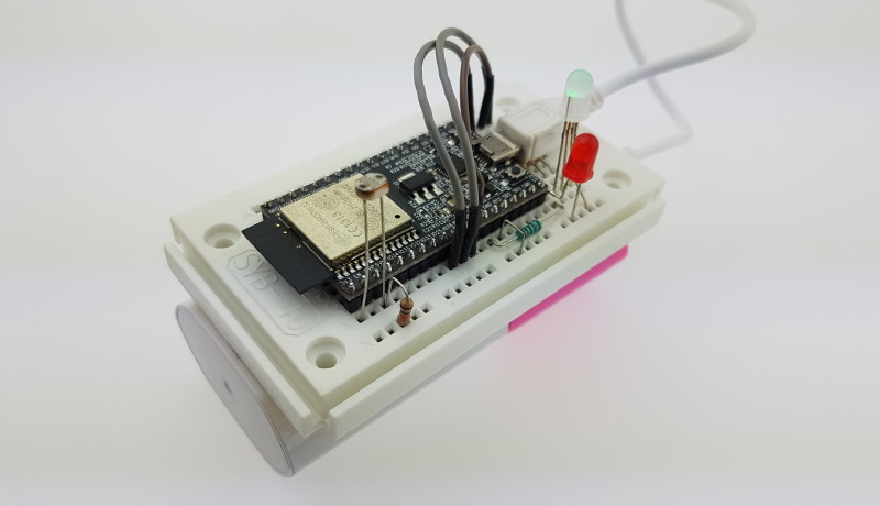
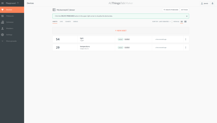
To measure something useful I connected a light-dependant resistor to pin 36 of the ESP32 DevKitC (see wiring diagram).The standard Arduino analogRead(Pin) command can be used to read the voltage level at the pin. The ADC measurement range extends from 0 to 1.1 V and the measured value has a resolution of 12 bits. After measurement the program discards 6 bits to produce a value between about 20 and 63 which represents the ambient brightness level. This value is then sent to AllThingsTalk; using the sensor name ‘light’ bound in the SendSensorDateToATT(…) function in the MQTT-Topic. In instalment 18 of this series we sent continually incrementing (simulated) temperature values (with the sensor name temperature) to the server. This reason for this was to make sure everything was configured correctly; should you make an error when you enter the Device ID or Device Token, the AllThingsTalk MQTT broker will still accept the MQTT connect request. However when you now try to publish the sensor values they will be rejected. The MQTT Publish command does not provide any acknowledgement or feedback to tell if the value has been accepted. By using the value produced by a constantly incrementing counter we can be sure by checking the web page that new values are continually coming in from the sensor and the link is in order.
The MQTT and TCP Library
When you look at the sketch for this installment of my journey, you will not find details of the MQTT and TCP / IP functions. I have put these (similar to the RGBLED functions in the last episode) in a class library.
The code section
#include <TCPClient.h>
TCPClient attTCPClient = TCPClient();
#include <MQTTClient.h>
MQTTClient attMQTTClient = MQTTClient();
TCPClient attTCPClient = TCPClient();
#include <MQTTClient.h>
MQTTClient attMQTTClient = MQTTClient();
binds the libraries and generates the necessary objects for access to the respective functions. In the Setup function you can find the line
attMQTTClient.myTCPClient = attTCPClient;
This passes the TCPClient object to the MQTTClient objectwhich is used in the main program for connection via TCP. The MQTT library also accesses functions of the TCP / IP library. Network and protocol software often has this sort of hierarchical structure; if these concepts are new to you its worthwhile looking into the analysis and design of object-oriented programming.
An ESP32 sensor node prototype
Try it out! All you need is a prototyping plug board and a few general-purpose components that are likely to be kicking around in your box of spare parts. The Library sub folder included in this instalment’s download should be installed in the libraries folder of the Arduino IDE. Compile and load the program to the Arduino; when the green LED is lit continuously log in to the ESP32_MyJourneyIoT network and enter address 192.168.4.1 into your browser. Enter values into the text fields. In the ‘Device Token’ text field it is only necessary to enter the character sequence after ‘maker:’,the rest of the string will be added in the sketch.Now the RGB LED will start to pulse yellow and then switch to pulsing green. The sensor values should now appear on your ATT web page (see instalment 18) providing you correctly entered the Device ID and the Device Token values.
I now hooked up my prototype to a USB power bank so I have a neat little IoT device that autonomously sends measurement values of the ambient brightness to the Cloud.
Stay tuned for the next instalment!
Read full article
Hide full article
Discussion (0 comments)