
Review: The JOY-iT JT-HD35 Electronic USB Load
on
When I saw this little device called the JT-HD35 from Joy-IT on the Internet, I was curious. An electronic load for the USB port? Another crazy idea dreamt up in the Far East! But as I read in more detail what this test unit can do, it all became a bit clearer. It can be used to test the performance of all types of USB ports. This is not only useful to test a port designed into a product for production but can also be used to ensure that an off-the-shelf charger really can provide the power quoted in its spec sheet. I have already reviewed another USB test device from Joy-IT called the UM25C — but this one here is a different kettle of fish with different capabilities.
Electronic USB Load: Features
The Joy-IT JT-HD35 is a compact, electronic USB load resistor able to measure and display the output power up to 35 W from a USB port or charger. It can test the output of a standard 5 V USB charger as well as those compliant with some of the more recent fast-charge standards.
The key features of this unit are:
- Operating voltage: 4 to 25 V (DC)
- Load current: 0.25 to 5 A
- Power: max. 35 W
- Indicators: 3 status LEDs (green, blue, red)
- Display: 4-digit 7-segment display LED, red
- Operation: 3 buttons, 1 multiturn potentiometer (load current adjust)
- Connections: USB 2.0, Micro-USB, USB-C
- Fan: 40 mm, 0 to 8000 rpm, temperature controlled
- Dimensions: 84 x 41 x 28 mm
- Weight: 52 g
Unboxing
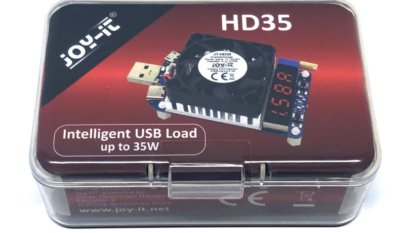
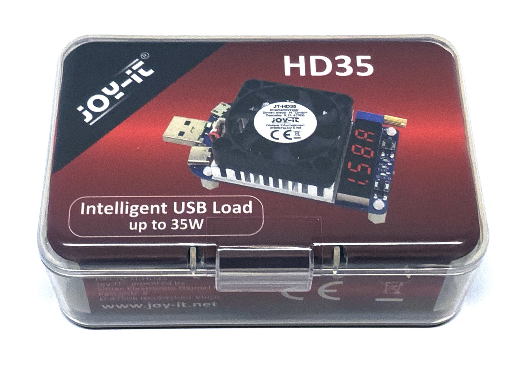
The load tester consists of a single board and is supplied in a translucent plastic box (Figure 1) with the picture on the lid showing what is inside. Apart from the USB load tester board there is no documentation or links to any sites where the documentation can be downloaded. The underside of the box is printed with the main features of the load tester but again no links (Figure 2). This is no great loss because it’s no problem to Google the company name and find the user manual for this device in PDF format.

I prefer to store this type of document in an ‘Instructions’ folder on my PC; it saves tedious searches by hand — and a PDF is ideal as it can be searched for keywords in most cases. First of all, I was keen to see how far I could use the device without resorting to the manual.
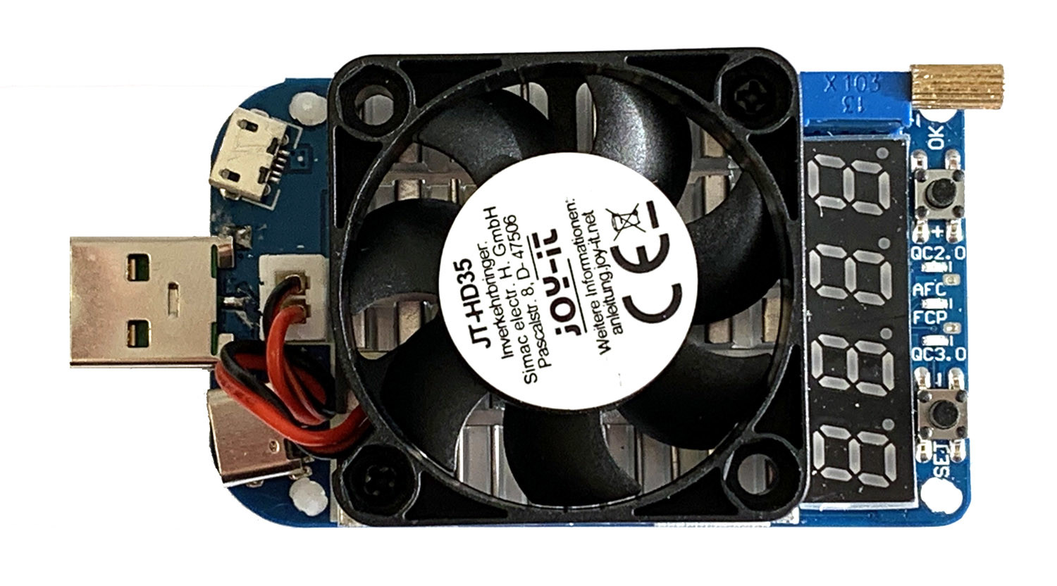
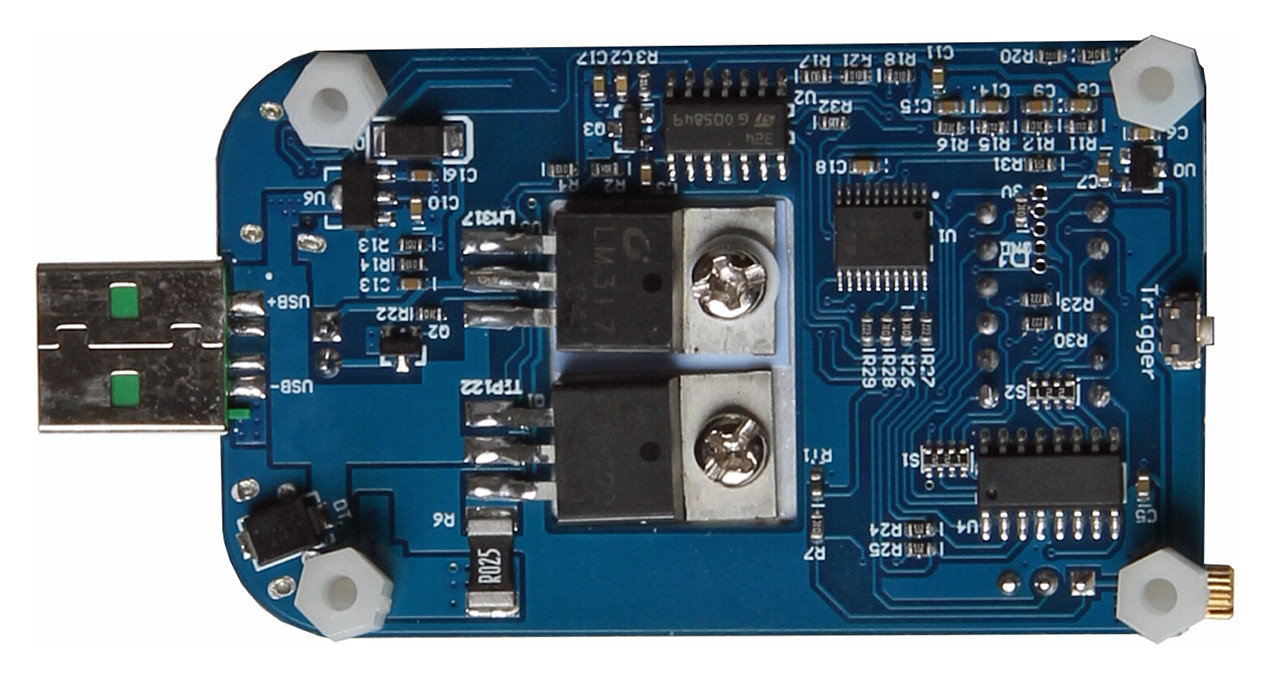
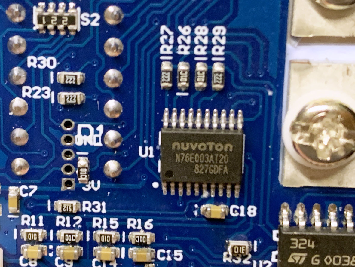
Figure 3 shows what’s in the small plastic box. The unit consists of an assembled PCB with a heatsink and fan fixed in place using only two screws. On the underside shown in Figure 4 you can see the TIP122 power Darlington and an LM317 regulator which are mounted on the underside of the heatsink. The NPN Darlington transistor is rated at 65 W max. and is probably used as the variable load to dissipate the power. Also on this side is a microcontroller labelled U1 = N76E003AT20, which is a small extremely low-cost (€0.28) 8051 derivative. Spaced out across the board are a sprinkling of peripheral chips and passive components. Because the writing on these tiny SMD components is not easy to read, I usually take photos of them and enlarge the result (see Figure 5).
Testing, testing…
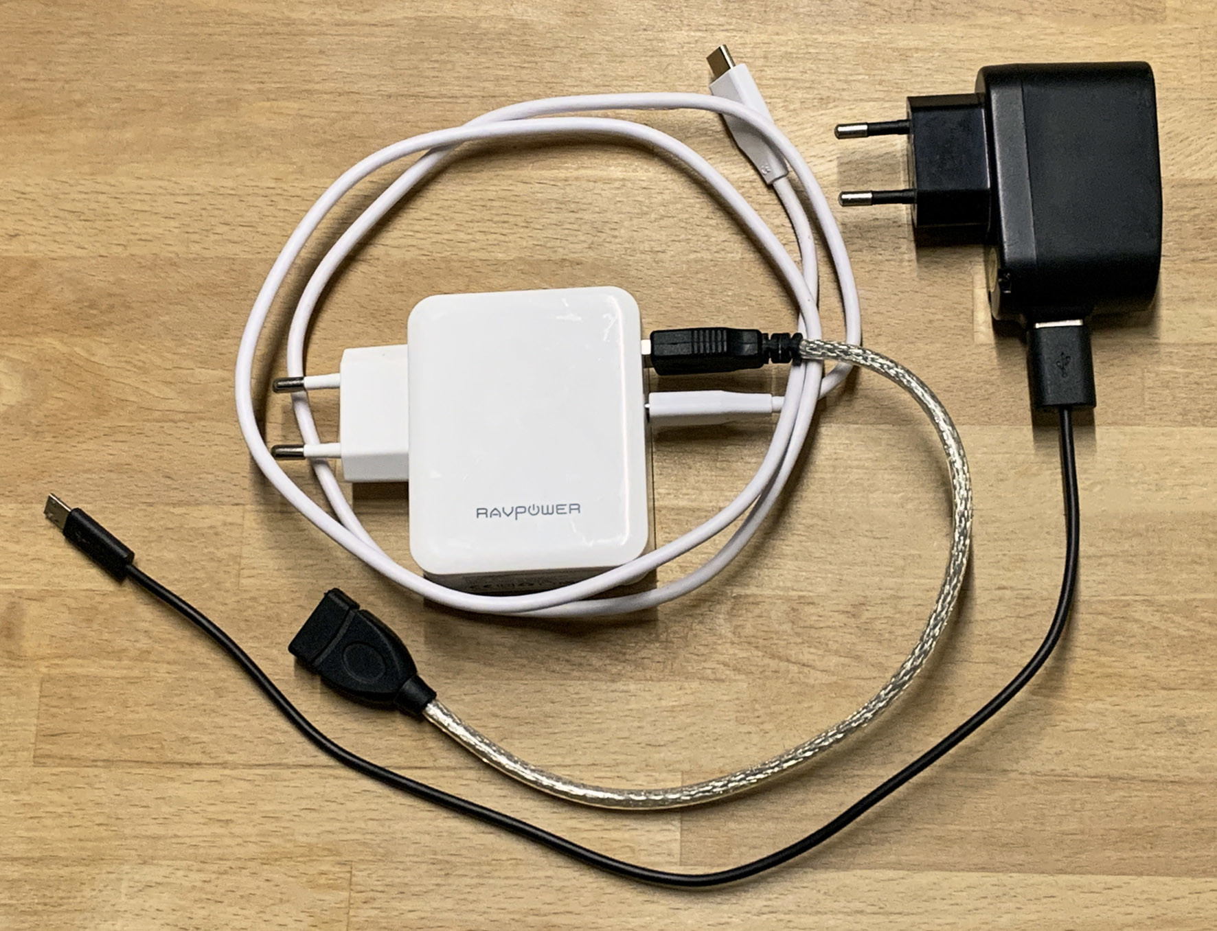
I selected two power supplies/chargers with three cables as guinea pigs (Figure 6) for the USB load tester. The little black one on the right with the micro-USB to USB-A cable is a cheap standard charger with 5.1 V and 1 A load capacity, as it used to come with many (old) smartphones. It cannot deliver anything much more than five watts. The white ‘smart’ power charger from RAVPower is surrounded by a USB-A extension cable and a USB-C cable. It supplies 5 V at 2.4 A from its USB-A socket and not only 5 V at 3 A from the USB-C socket, but also 9 or 15 V at 2 A or 20 V at 1.5 A thanks to its compliance to QC 3.0. The total power output amounts to 36 watts, which ties in nicely with the rated power handling of the JT-HD35.
After switching on, when connecting to the black charger, the voltage is shown in two digits on the display, i.e. about ‘5.1 V’. After a little erratic operation of all the pushbuttons, I think I got some idea how this thing works: pressing the ‘SET’ button cycles the display to show voltage, power (initially ‘0.0P’) and current (here flashing ‘1.00A’). Now if you press the OK button once, the current setting value stops flashing and remains constant. Then after about 20 s the cooling fan kicks in. This indicates that when the displayed current is flashing it shows the required value of load current but without the load connected. When the displayed current is continuous it indicates that the load is connected. Another press of the ‘OK’ button removes the load and sets the display value flashing again.
By adjusting the multiturn pot setting while testing the small black charger under load I increased the load current to 1.1 A and noticed that the output voltage dropped to 3.5 V. It was reassuring to find that the charger has some built-in over-current protection. It was also interesting to see that micro-USB connector is unsuitable to deliver high levels of current. Even with a current limited to 1 A the voltage drop across the connector resulted in a measured supply at the load of 4.9 V, whereas the USB-A extension cable used with the same power supply delivered 5.0 V.
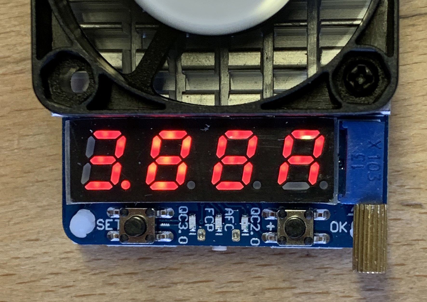
Now with the USB-A socket of the RAVPower unit connected to the load tester via a USB-A lead its current limit starts to activate at around 3 A. Connected via the USB-C cable, it was possible to crank up the load current to 3.88 A before the power supply shut down (see Figure 7). It looks like the technical spec for the RAVPower charger is quite modest when it comes to its maximum output current rating.
And now?
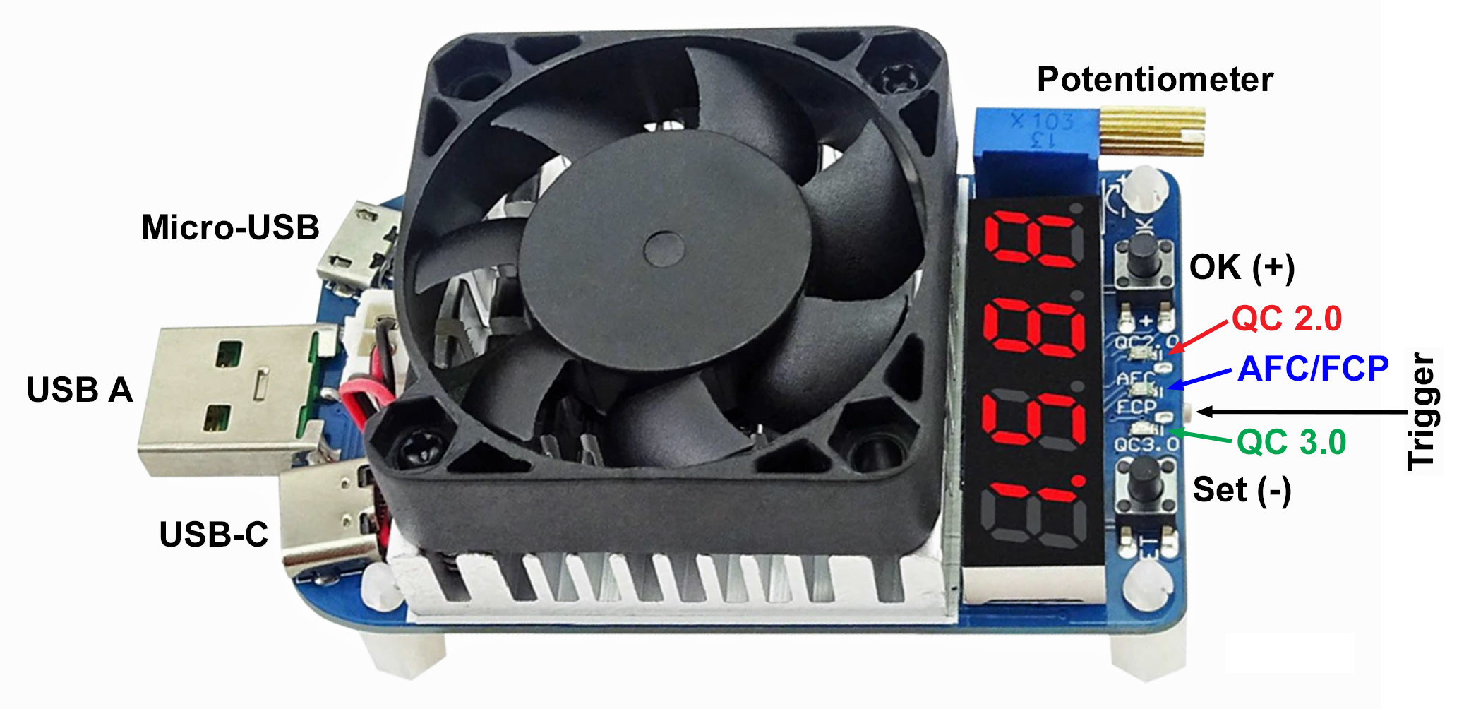
After testing it with 5 V USB supplies I wanted to move on and try various other voltages according to QC 2.0 or 3.0. At first I wasn’t sure how I could change the mode but after searching through the manual it became obvious I had overlooked a pushbutton on the underside of the board. This is the ‘trigger’ button — used to activate the curiously named ‘trigger/decoy’ feature. I guess the JT-HD35 could be thought of as a kind of decoy device which sends appropriate acknowledgements to the charger, to make it switch its output (surely ‘Mode’ would be a better label). I added clearer labels to identify the button in the photo shown in Figure 8.
A long (2 seconds) press of this pushbutton switches the unit out of its default (5 V) to the other modes. The display should first show ‘-5.0’ to indicate it is in QC 2.0 mode. The red LED flashes and you can use you the ‘+’ and ‘-‘ buttons to adjust the charger voltage output in steps through 5/9/12/15/20 V. Further presses of the trigger push button get into the other modes including ‘AUTO’ which can identify if the charger has a quick charge function — in this mode message exchange can take up to 25 s to complete. Although USB was originally conceived as a universal interface to reduce e-waste, various companies such as Huawei, Samsung and Apple now offer fast charge schemes which are not interoperable. A recent vote in the European parliament however returned a massive majority in favour of making iPhones and Androids use the same charger — this could mark the end for Apple’s Lightning Cable in Europe when the law comes into force in the summer.
According to its specification the JT-HD35 can provide load tests for chargers designed for standard QC2.0, QC3.0, Huawei’s FCP fast charge system, Samsung’s AFC9 and ‘other quick charge modes’ although it is not specific what these other standards are. Without any of these quick chargers to hand I was unable to test this feature of the device.
Without reference to the manual, I certainly struggled to change the operating mode. Operation of this electronic USB load was (for me) not entirely intuitive. For my needs I am only seldom likely to make use of a test device like this. Chances are when I come to use it again in three months time I will have forgotten how it works.
Conclusion
All in all, this inexpensive electronic USB load is functional and does exactly what it's supposed to do. The decision not to include a printed copy of the operator’s manual is a big thumbs-up to help reduce unnecessary waste. The standard of documentation is quite poor and just about covers the basics of operation. This is only to be expected for such a low-cost piece of test kit that only gets occasional use. When it comes to displaying the word ‘Auto’ or ‘OTP’ I think even I would be able to work out a better representation of the letter ‘t’ on a 7-segment display.
There is always room for improvement… I would like to see better signage for the trigger pushbutton and a better red filter over the 7-segment display to improve readability. All in all, this USB load does what it says on the tin. It is inexpensive and, thanks to the fan, can dissipate high power levels for extended periods. The maximum power handling is 35 watts and it did not get over-warm when I ran it at 30 watts so it should be able to take whatever the current USB charging specification can throw at it. If you think you can make use of this electronic load to test a USB power supply this is a good, convenient low-cost solution. You could hardly build one more cheaply yourself from scratch.
Discussion (1 comment)