
Review: JOY-iT RD6006 Benchtop Power Supply Kit
on
Even if it is true that engineers and hackers can never have enough power supplies, I am now beginning to run out of bench space. I had good feedback after I reviewed the small linear PeakTech 6080 A lab power supply (see review), and was keen to look at a more powerful benchtop power supply which employed switched-mode technology. I looked at the RD6006 benchtop power supply - this time from Joy-iT. One reason to choose this model is that it is supplied as a kit of parts and not as a finished piece of equipment. As any true electronicist or maker will tell you, putting something together yourself always gives that added level of satisfaction to any project (especially when it works).
The kit
The Joy-iT JT-RD6006 DC Power Supply Bundle is available to order from the Elektor Store. It is not a conventional kit where you would be expected to solder components onto a PCB. This is more of a bolt-together assembly job; all the supplied modules just need to be wired together inside the enclosure using just a screwdriver and without the need to power up a soldering iron. The individual modules have already been tested and calibrated, but more on that later.
Key features of the Joy-iT JT-RD6006 DC:
- Mains voltage: 115/230 V (standard)
- Output voltage: 0 to 60 V
- Output current: 0 to 6 A
- Maximum output power: 360 W
- Output voltage resolution: 10 mV
- Output current resolution: 1 mA
- Charging function: 0 - 9,999.99 Ah; 0 - 9,999.99 Wh
- Residual output ripple: 100 mVPP (at max. load)
- Display: 2.4” colour LCD
- Operation: keypad, rotary encoder, USB, Wi-Fi
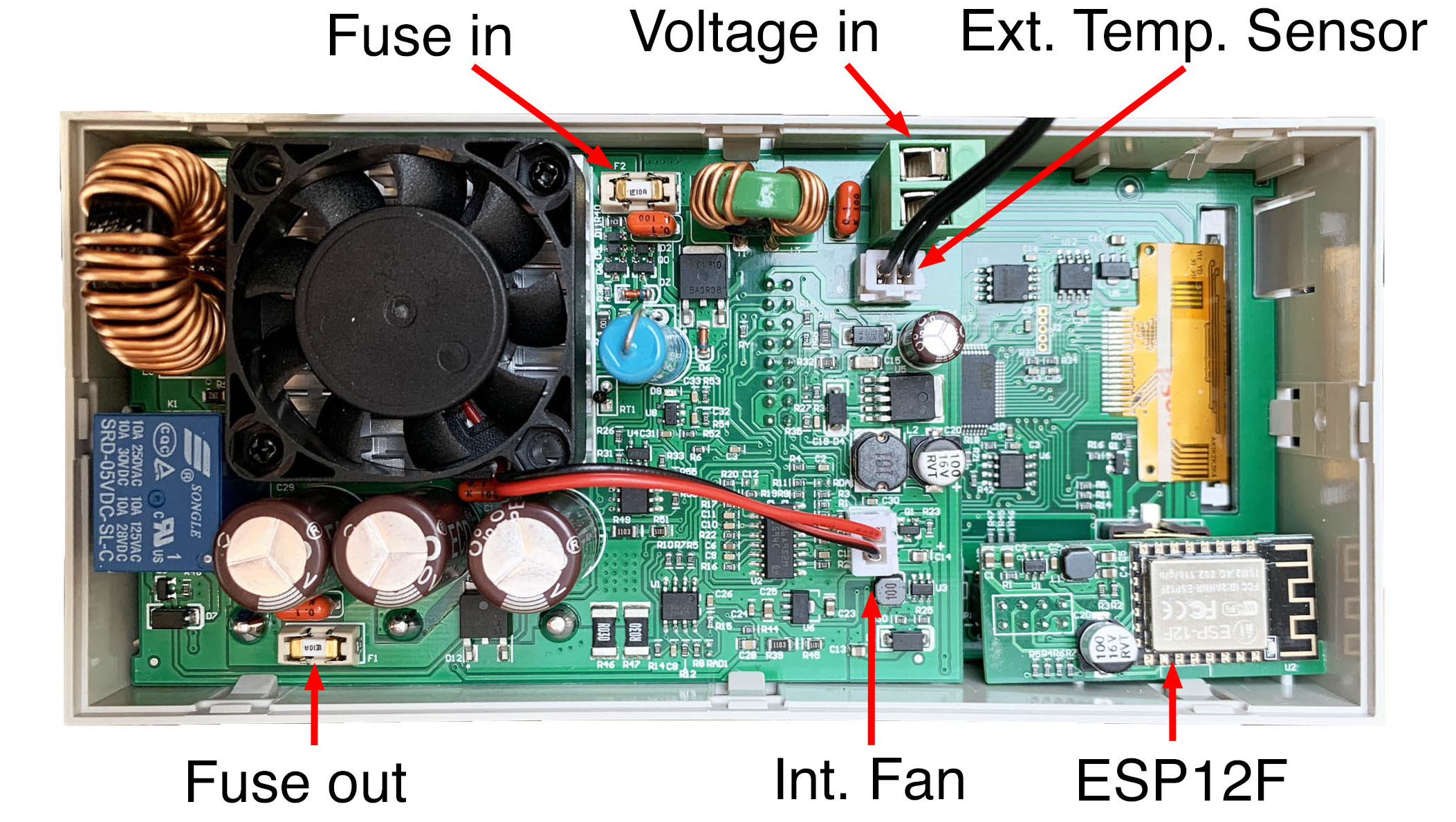
- Wi-Fi module: ESP12F
From its spec this benchtop power supply offers quite impressive capabilities. It is more capable than an older digital 480 W benchtop power supply of Chinese provenance I have. The JT-RD6006 is even a little cheaper at €175.46 (for Elektor members). An output capability of 60 V and 6 A will probably be sufficient for around 95% of all typical applications in the lab.
Unboxing
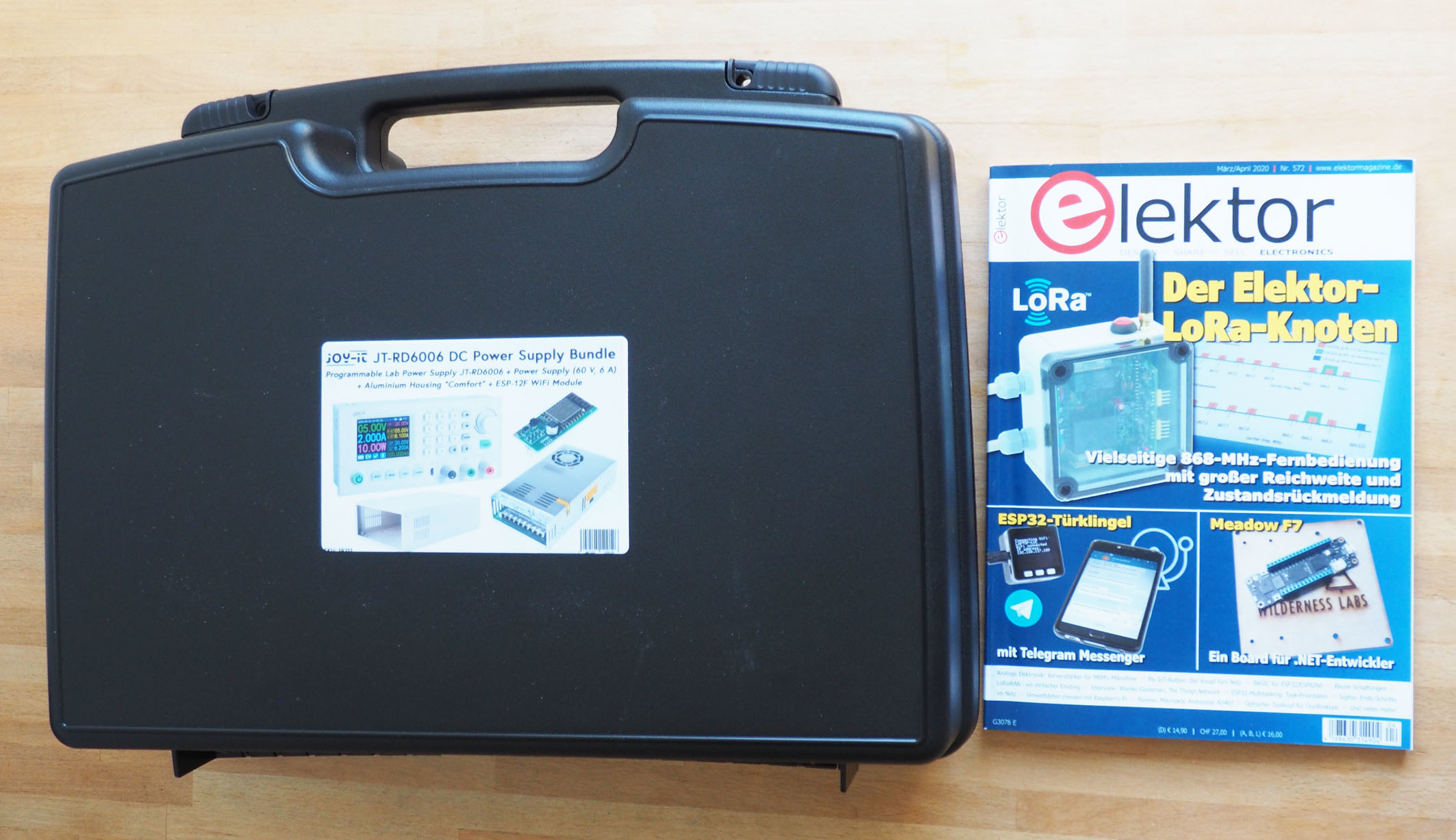
The power supply bundle comes in an impressively large box measuring 50 x 36 x 15 cm (Figure 1).
Inside the three 'packages' (Figure 2) are many smaller parts (Figure 3). I really was beginning to doubt whether I would be able to get away without using any solder.

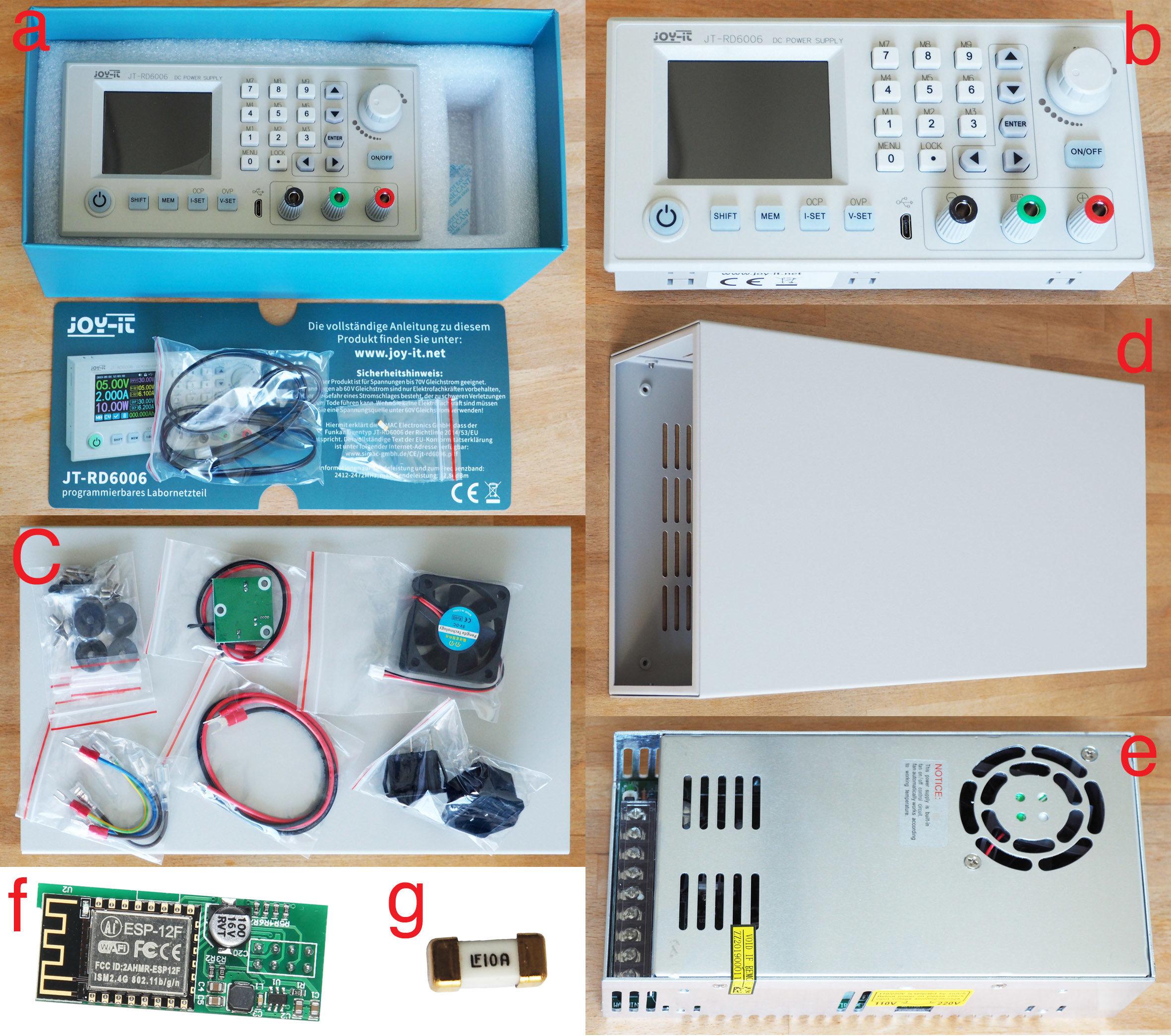
As you can see in Figure 3a, there are no instructions included and unfortunately no direct URL pointing me to some; only a link to the manufacturer's website. To resolve this, Google RD60006 and you will find the operating instructions as a .PDF file with a click on a picture.
Once you have a copy of the file you will see it’s just an operating manual with no assembly instructions. The assembly and wiring of the many parts is fairly logical if you have an engineering bent, but not entirely trivial.
Assembly instructions
In the absence of supplied assembly instructions these guidelines should help you through. All you need for this is a medium-sized Phillips screwdriver, a very small flat-bladed screwdriver and some small needle-nose pliers for gripping the nuts. I can confirm that you won’t need a soldering iron; I was able to put it all together reasonably quickly on a kitchen table.
First remove the eight M3 x 5 countersunk Phillips screws with which the cover of the gray sheet metal housing is attached. The mains switch and IEC socket can now be inserted into the cutouts on the rear panel (Figure 4). The switch snaps into place, but the power socket requires two M3 screws and nuts. Here the needle nose pliers are used to hold the nuts while tightening the screws. Finally, the small circuit board with the fan controller using be attached using three black M3 x 5 screws.

Mounting the fan in the case is a bit tricky: the M3 nuts fit nicely onto the fan frame but the nut recesses are circular so the nuts just rotate and won’t tighten unless you can pinch them somehow. The space around the nut is too tight for my needle-nose pliers to gain purchase. Figure 5 shows the blade of a very fine screwdriver being used to stop the nut turning. The fan is positioned so that its cable is on the right as shown.

Now you can screw down the open-frame power supply (Figure 3e) into the enclosure using four M4 x 6 pan-head screws. Make sure that the connections of the power supply point to the rear (left). The four rubber feet can be fitted in the corners using M3 x 5 screws. Figure 6 shows how it should look.

Figure 7 shows how all parts are wired. The terminals on the industrial power supply in particular should be tightened well, but not too tightly.
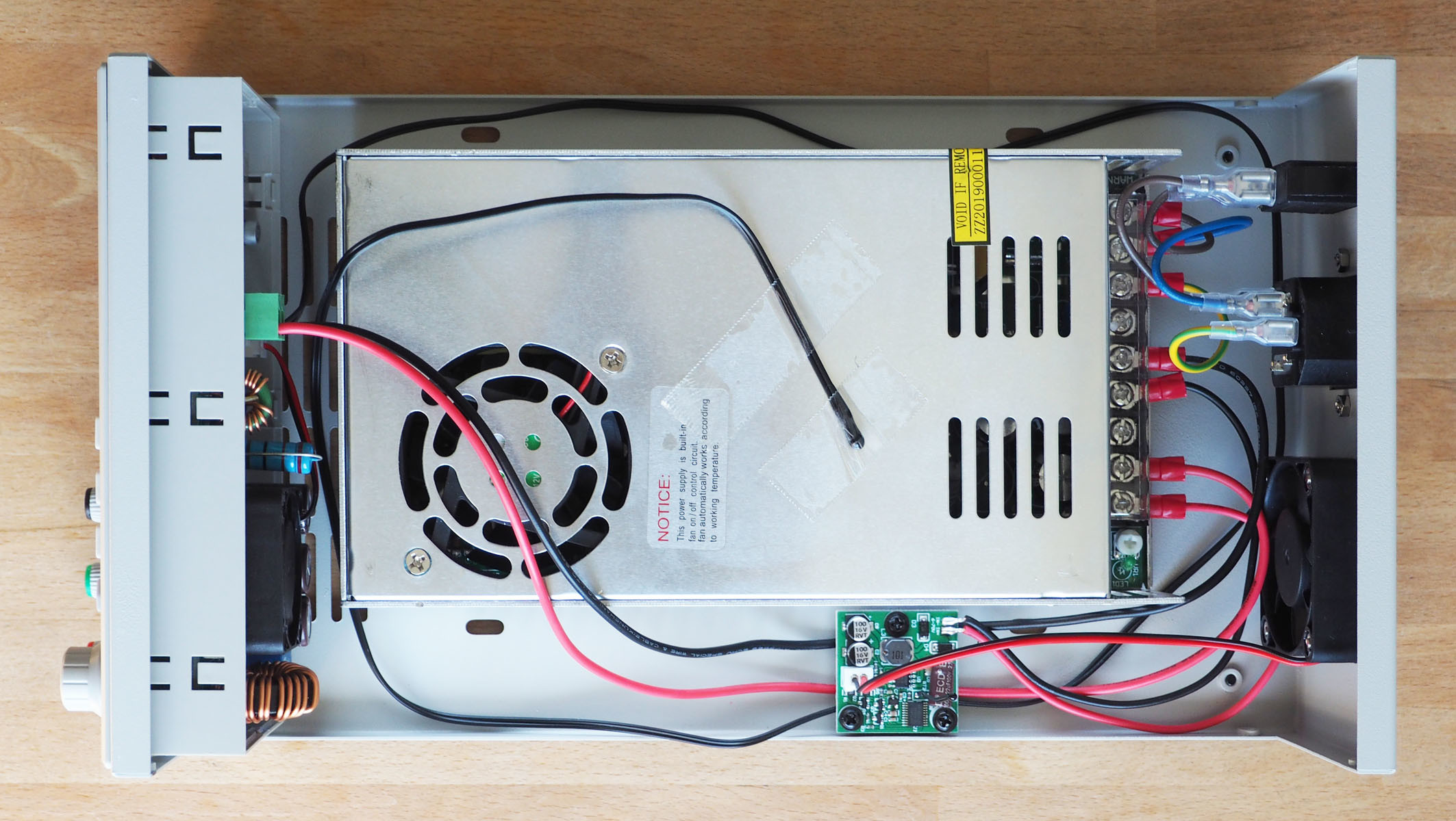
Figure 8 shows the close-up. You should always double-check when wiring equipment which will be powered from the mains. All wires are supplied finished to a suitable length with their ends either tinned, provided with cable lugs or plugs.

Before you push the front module into its recess in the housing, as shown in Figure 7, you should plug the supplied ESP12F Wi-Fi module (Figure 3f) onto the back of the front module board. Figure 9 shows the front module from behind with the Wi-Fi module attached. Under this module is a battery compartment to accept a CR1220 button cell. this does not need to be fitted. The green 2-pin terminal block labelled 'Voltage in' can be removed and screwed with the longer red and black cable and then plugged in again.
If you now screw the cover back onto the housing, the finished benchtop power supply should look like the image in Figure 10. It is interesting that I have a few screws and two cable-end lugs left over after the build. There is no power cord included in the kit.

Operation & adjustment
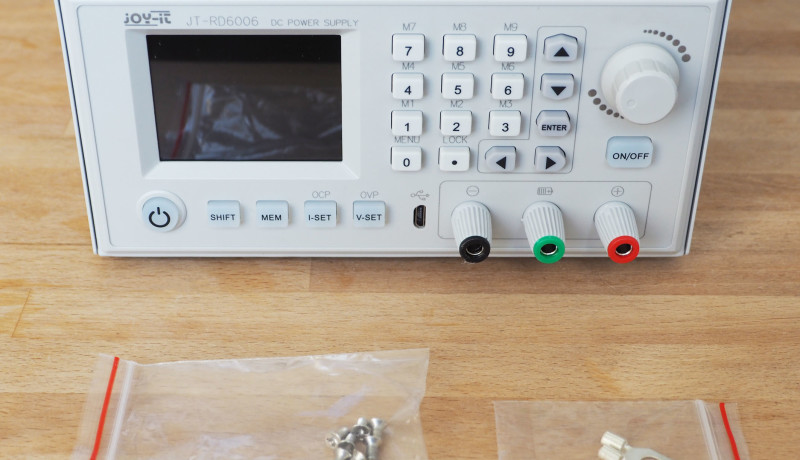
Figure 11 shows four different operating states. But before I describe them, a few more comments: the coloured display is very informative and shows more information than strictly necessary. In the standard mode shown (there is another one that shows ‘trends’) you can view the current four-digit values of voltage (green), current (blue) and power (red) on the left. At the top right you can view the input voltage to the regulator section. This is the output voltage of the industry-standard closed-frame power supply which is displayed here as the ‘INPUT’. This is followed by the set voltage (U-SET) and current (I-SET) and then the set protection against overvoltage (OVP) and overcurrent (OCP).

In Figure 11a, the current values are all still zero since the output is switched off. When you press the ON/OFF button on the right beneath the rotary encoder, it lights up and the output is switched on. In Figure 11b you can see the currently applied and actually measured voltage of 5.00 V, which is exactly the same as the requested set voltage. No current flows without a load - the power supply is in constant voltage mode (CV at the bottom in white). My measurement showed exactly 4.996 V, which amounts to a negligible error of -0.08% indicating that the power supply was properly calibrated. My older 480 W power supply can only show output voltage and current levels, here you can see any differences, and that's useful.
Figure 11c shows my attempt at setting the maximum possible output voltage but only achieving 59.18 V instead of the rated value of 60.00 V. Why the discrepancy? The complete PSU is made up of an industry-standard closed frame power supply outputting a fixed 60 V supply fed to a regulator section. The regulator takes this 60 V and outputs a voltage according to the values between 0 and 60 V dialled up on the front panel controls. A small voltage loss introduced by the regulator means that its maximum output voltage cannot be as high as the input voltage. We can remedy the situation by tweaking the output voltage from the closed frame power supply to just over 60 V. I increased this input voltage by adjusting the small, white potentiometer at one end of the terminal strip shown in Figure 7.
Now with the input voltage adjusted to 61.5 V you really can set the output voltage up to 60.00 V. In order to avoid any problems under load, I increased the value further to give a small reserve. Figure 11d shows that an input voltage of 62.56 V is sufficient to ensure 60 V output even under full load. At 5.885 A the output is measured at 59.96 V and cables to my load resistors became warm. My multimeter measured 59.94 V which indicates a completely negligible error. So by making a few adjustments the benchtop power supply runs quite perfectly. The cooling fans are also barely audible and the internal temperature only reached 29 °C after 15 minutes at 353 watts output power.
Output noise levels
It is generally true that the output voltage produced by a budget-level switching power supply will be electrically noisier than that produced by a supply designed using linear technology. I hooked up my 'scope to the output terminals to measure the noise levels. Figure 12 shows noise on the output voltage under four different load conditions. The first thing to note was that no 50 or 100 Hz signal was discernible on the output voltage - so far so very good. Using AC coupling and by increasing the sensitivity of the scope’s input amplifier I was able to see noise on the output DC level. I adjusted the trigger level and time base setting until the noise waveform was stationary on the scope display. With the time base set to 2 µs/div I could see periodic signals with a repetition rate of about 115 kHz — this is likely related to the switching frequency of the regulator. My scope shows the noise waveform on the output voltage level with no load connected. Ripple and noise amount to around 22 mVpp (Figure 12a).
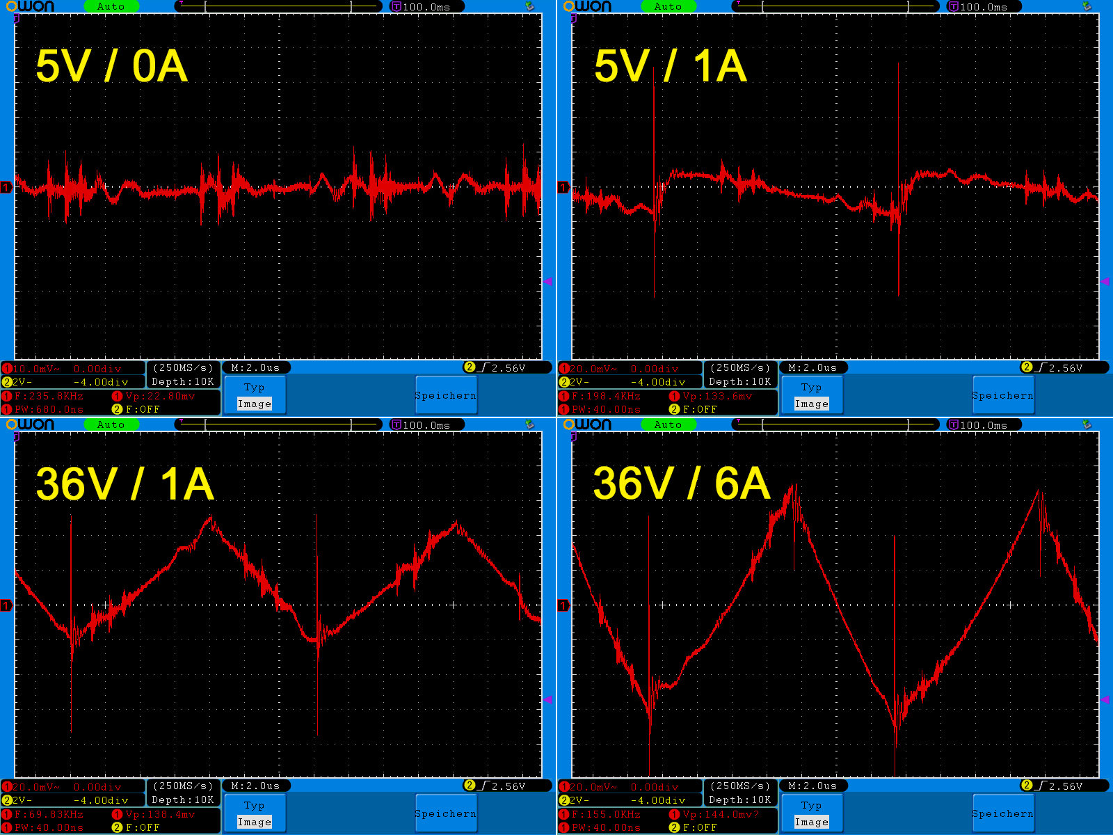
Using a relatively small 5 W load (Figure 12b), the repetition rate of the noise spikes drop to around 70 kHz with an amplitude of 130 mVpp. Additional filtering at output would help reduce the noise amplitude. At a moderate load of 36 W (Figure 12c), the repetition rate of the spikes is the same, but the noise waveform is more triangular as more energy is delivered to the load and supplied by the regulator resulting in a noise level of about 70 mVpp. By increasing the load power to 200 watts you can see in Figure 12d that the amplitude of the triangular noise waveform almost doubles to around 130 mVpp. This exceeds the maximum 100 mVpp specified by the manufacturer but it would be acceptable for the majority of tasks undertaken by a high-power digital benchtop power supply.
Conclusions
I did not try to control the power supply remotely via USB or WiFi. The information given in the manual was rather cryptic and to be honest I’ve never had a need to do anything like that either. For my needs I like to be able to adjust voltage and current limit by hand directly via the front panel controls. I simply ignored the other built-in luxury features because I can't imagine when I would need them. This benchtop power supply is also said to be able to charge batteries at defined values. There is even a separate green output socket for the positive pole connection. Here the current is switched off when it falls below 10 mA so that the battery cannot be overcharged. I couldn’t work out why this feature requires a dedicated socket. To understand how the battery charging feature works we need the skills of an Alan Turing to decode the relevant passages in the German manual. The English version doesn't make much sense either; it was probably translated from Chinese too.
As far as its features are concerned, I liked this benchtop power supply better than the one I have been using for years. The display in particular is great because it shows target and actual values at the same time. I also like that (up to ten) presets for voltage and current limit can be preprogrammed and selected easily. The setting of the values is via a rotary encoder (fast & intuitive) or via the keypad (exactly) is also very useful. I like the ability to adjust the voltage and current limit very precisely. The electrical noise level on the output voltage is higher than can be expected with a linear power supply, but in practice (except when powering sensitive RF parts) it is not high enough to cause problems. After switching on, the microcontroller boots really quickly so that the power supply is ready for use within a second if you switch off the display. For me that’s a revelation; my old heavy-duty power supply, takes almost 15 s before its ready to go. The price-performance ratio of this supply is good and if any component part fails it will be easy to replace individual parts.
Now to the downsides: It’s annoying that no mains kettle lead is included in the kit but even more frustrating is the poor quality of the documentation. This is however what we have come to expect from all budget-level equipment sourced from the Far East. It turned out that this was not too much of a handicap because control of all the supply’s basic features is fairly intuitive and I didn’t feel I needed the additional ‘mystery’ functions.
Can you help?
The operator’s manual for this power supply is blighted by incomprehensible gobbledygook. If you are able to work out all its special functions and rewrite the manual so that even I can understand it then you will be rewarded by receiving (for free!) the very power supply which was the subject of this review. First come first served, there can only be one winner. I can then let you know the status of this offer. The lucky entrant allows an edited version of the instructions to be published by Elektor and Elektor retains all publishing rights to the piece. As always the rights to appeal are reserved. Interested?
Update:
The power supply found it's fan now. We will publish the better manual soon.
Discussion (6 comments)