
130109 Lux meter 1 lux - 100 klux
130109 Lux meter 1 Lux – 100 kLux(Designed by Karl-Anton Dichtel) The following is based on text and information the author provided. Due to the ban of incandescent lamps in the EU a lot of new lighting alternatives have been developed like halog
130109 Lux meter 1 Lux – 100 kLux
(Designed by Karl-Anton Dichtel)
The following is based on text and information the author provided.
Due to the ban of incandescent lamps in the EU a lot of new lighting alternatives have been developed like halogen, fluorescent and led lamps. The different data about efficiency, color temperature and light output supplied by the manufacturers is not always conclusive. The user just wants to know how much light the new lamp will produce on his desk or in the house. With this Lux meter it is easily measured. Center of the meter is of course the sensor, in this case a BPW21R. It has a filter so that the measured brightness and color sensitivity largely corresponds to the human eye. If you operate the photodiode in short-circuit operation, the current will be proportional to the applied brightness in lux over a wide range.
The operating mode "short-circuit" for the sensor BPW21R is done by the operational amplifier MCP6061. This opamp has an offset of only 150μV and an input current in the pA range, so no additional measurement error arises. Since the range of the human eye may vary between <1 lux (full moon 0.25 lux) and a sunny day with approximately 100k-Lux, this is also the range we expect from the circuit. If you switch the feedback resistor according to the brightness between 200 kOhm and 2kOhm by means of a low-power bistable relay, the following ADC only has a dynamic range of 1: 1000 to process. In addition, the ADC has a by software switchable precision preamplifier of x 1 to x 8, making it possible to have a high resolution over the entire range. The ADC with TWI interface is operated and read with +/-15 bit resolution by an Atmega328.
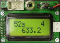
The following measuring ranges are shown on 2 x 8 LCD (in the second line):
The following measuring ranges are shown on 2 x 8 LCD (in the second line):
0 to 1.00 - 10.00 - 100.00-1000 .0 (Lux) - 10,000 - 100.00 (k-Lux)
Switching is done at 90% and 110% of the range value automatically.
Switching is done at 90% and 110% of the range value automatically.
After switching on (button S1), the battery voltage is measured and displayed for 1 second, then displays seconds in the first line and switches off after 60 seconds. Similarly, the measured values are in second intervals (38400 baud) output via a 5 volt RS232 interface. Also an offset calibration is started at power-on:
- Before programming usually EEPROM and flash memory are deleted. Then the EEPROM cells are set to $ FF.
- After programming, the program starts, reads the cell for the offset value in the EEPROM.
- Is it equal to $ FF, the offset measurement is started in both ranges (without BPW21!, remove JP3) and the measurement values are stored in the EEPROM.
- The measured values are immediately copied to the RAM and included in the calculation of the measured value.
- Does the EEPROM memory cell at startup not contain the value $ FF, then the normal measurement program starts.
- After the value 0.000 appears in the second line, jumper JP3 can be placed and the Lux meter is ready.
- "Power on time" and "distance of each RS232 values" are constants in the program of the Atmega328 and may be changed if needed (this means editing the source code and reprogram the processor yourself!). The processors memory is not fully used and offers options for extensions. Also interesting is the output of operational amplifier (K2). After connecting an oscilloscope it can be seen that conventional fluorescent lamps deliver their light with 100 Hz frequency.
The software was created with the free AVR Studio (v4.18) in C. The crystal frequency of 10.24 MHz divided by 1024 is used for the interrupt and a 5ms clock for the relay control is derived. Through further dividing a 0.5-second clock is created with which the entire process is controlled. The main program is called only once during startup and then runs in an empty loop. The software for the LCD driver comes from http://www.mikrocontroller.net/articles/AVR-GCC-Tutorial/LCD-Ansteuerung and for the TWI interface has an adapted version of the project "TWI Driver for Weather Station". As a relic of the predecessor project, software for an encoder and a button still exists. Similarly, 3 port pins are still free. The actual C program is commented in "English" as detailed as possible. It allows the convenient use of the lux meter and because of the Auto Range mode, no further operation is required.
There are some additional features. Below 64 Lux the backlight is automatically turned on (if jumper JP2 is placed) and then adapted to the measured brightness. When the device is connected by means of a RS232 link to a PC, e.g. a TTL-232R-5V cable from FTDI or our FT232R USB/Serial Bridge/BOB (110553-91), an additional calibration mode can be initiated (in any terminal program, we used HTerm 0.8.1beta).
It is possible, using a correction factor, to compensate the tolerance of the sensor BPW21R. A calibration with high resolution is possible over a wide range (2 bytes = 65536). The current routine uses the stdio.h library in AVR Studio 4 and reroutes the program inputs and outputs accordingly. This means that printf() and scanf() can be used, and asynchronous communication between PC and ATmega328 processor is possible in the background.
At program start in the EEPROM stored values for calibration and offset are copied into RAM during initialization. If the validation at first program run shows that the EEPROM contains no values (= $ FF), the default value for the calibration is saved. The offset measurement is started, and this measurement result is stored in the EEPROM. To distinguish the RS232 output between normal measurement mode and the programming mode, the variable "progr_mode" is used. When the program starts this = 0 and through RS-232 takes the output of the measured values every second. If 1 is entered, settings can be changed in the dialog from your PC. At present this is only the calibration of the LUX indication with a factor.
Programming a new processor:
- First transfer the file main.hex to the Lux meter
- The program IRQ start the first time and the program notices that the EEPROM memory is empty ($ FF).
- The default value x1 for display is stored in EEPROM in 2 bytes and copied into RAM. The conversion into a floating point value for the calculation of the measurement values takes place. (1 LUX / 9nA the BPW21 => 10000 = x1)
- The offset values of opamp and ADC (without BPW21R) are measured, displayed and stored in the EEPROM.
- The display will then show the corrected measured values and outputs them at one second intervals via RS232. Here, the semicolon as CSV delimiter is used as well as additional TCCs to improve readability on the issue. If familiar with Excel one can easily adjust these data for further processing.
Calibration by reference light source or calibrated measuring device:
1- By comparing the lux meter with a reference, the correction factor is calculated manually. If the display of the LUX meter is a factor of 2 too large, the correction factor = 0.5. As 5-digit integers are used for input, the number to be entered is 05000. Is the reading e.g. when using a milk glass plate as a diffuser only 0.567-fold, is the correction factor 1 divided by 0.567 = 1.7637. So enter 17637 (max. 2EXP16-1).
2- After turning on, the LUX meter is waiting in the background to one (only one!) number entered by means of an RS232 any terminal program. Only if 1 is entered, the program switches the RS232 interface to the input of the calibration factor.
Output:
Mode 1: Calibration - Input 5 digits or ESC with #
actual calibration factor = 10000
Input Calibration:
3- Now type in the 5 digits, these will be applied after the 5th input and the normal measurement mode is started again.
4- If a new correction factor has to be entered the processor must be reset and this can be done numerous times. Resetting the processor can be done by briefly shorting pin 5 and pin 6 of ISP header K1 (the two pins next to the sensor (D1) and enter a 1 again.
5- The value entered for the calibration remains valid until it is cleared of the Flash and EEPROM memory and the reprogramming of the IC.
Benchmark: Testo 540
We did some measurements and compared our lux meter to a reasonably priced light intensity meter from Testo, the Testo 540. Without the additional correction factor the meters only differ about 3 to 4 percent from each other when tested in a room with the lights off (108 Lux instead of 105 Lux) or in the sun (65 kLux instead of 63 kLux). In our office with fluorescent lamps the difference is rather large, about 30 % (1115 Lux instead of 1600 Lux). We suspect the deviation to come from the light not being evenly spread and is not pure white but warm (reddish). Also the Testo 540 has a milk white spherically plate in front of the sensor. So what reading is the accurate one in this particular case?
Current consumption is about 14 mA when the backlight is not on. Just as the backlight is turned on (automatically) the current consumption is at its highest (about 33 mA). If the light intensity decreases further the backlight is dimmed (T3) to adjust it to the measured level of D1. If the light is virtually zero so is the backlight current. For experimenting purposes and in case one wants to program the microcontroller themselves the lux meter can be turned on permanently by placing jumper JP1. It prevents the meter being switched off by the microcontroller (T2 is no longer biased after 60 seconds after power-up). When the battery voltage drops the meter will operate perfectly to about a voltage of 5.5 V (that is with no backlight). A lower input voltage causes the output level of the voltage regulator to drop. Below 5 V input the display will start to fail.
K3 has the pin out of our FT232R USB/Serial Bridge/BOB (110553-91). To connect a 5V FTDI cable you have to build a little adapter (only 3 wires needed). Depending on the housing used for the lux meter consider soldering wires from the pads of K3 on the PCB to an external header. From top of the relay on the component side (where all the SMDs are) to the front of the display (mounted on the other side of the PCB, together with K1, JP1, JP2, S1, D1 and the connection for the battery) is about 25 mm in total. This depends of coarse how close the display is mounted from the PCB. Beware not to let the mechanical tabs of the LCD module make contact with the copper of the PCB. We used expensive pin headers with small rounded pins and special single PCB sockets to connect the display to the PCB. This makes testing easier when things need to be changed. But in practice 16 wires will do.
Bill of materials
Resistor
R1 = 200 kΩ, 1 %, 0W1, SMD 0603
R2 = 2 kΩ, 1 %, 0W1, SMD0603
R3 = 3k9, 1 %, 0W1, SMD 0603
R4,R5,R6,R8,R10,R13 = 10 kΩ, 1 %, 0W1, SMD 0603
R7 = 82 kΩ, 1 %, 0W1, SMD 0603
R9 = 33 kΩ, 1 %, 0W1, SMD 0603
R11 = 47 kΩ, 5 %, 0W1, SMD 0603
R12 = 33 Ω, 5 %, 0W2, SMD 0603
R14,R15 = 220 Ω, 5 %, 0W2, SMD 0603
P1 = 10 kΩ, 20 %, 0W25, SMD trimmer, top adjust (TS53YJ103MR10, Vishay Sfernice)
Capacitor
C1 = 1 nF, 5 %, 50 V, SMD 0603, C0G/NP0
C2 = 3u3, 10 %, 20 V, SMD Case A, Tantalum
C3,C5 = 470 nF, 10 %, 10 V, SMD 0603, X5R
C4,C13 = 4µ7, 10 %, 20 V, SMD Case A, Tantalum
C6,C12 = 10 µF, 10 %, 10 V, SMD Case A, Tantalum
C7,C14 = 10 nF, 10 %, 50 V, SMD 0603, X7R
C8,C9 = 22 pF, 10 %, 50 V, SMD 0603, C0G/NP0
C10,C11 = 100 nF, 10 %, 25 V, SMD 0603, X7R
Inductor
L1 = 10 µH, 20 %, 250 mA, 1.05 Ω, SMD 0603
Semiconductor
D1 = BPW21R, TO-5
D2 = TS4148 RY, SMD 0805
D3 = PMEG2010AEH, SMD SOD-123F
T1 = IRLML6402PBF, SMD SOT-23
T2 = BC848B, SMD SOT-23
T3 = 2N7002, SMD SOT-23
IC1 = ATmega328P-AU, SMD TQFP 32A
IC2 = MCP3421A0T-E/CH, SMD SOT-23-6
IC3 = MCP6061T-E/OT, SMD SOT-23-5
IC4 = LP2951-50D, SMD SO-8
Other
K1 = Box header straight, 2x3, 2.54 mm spacing
JP1,JP2,BT1 = Header connector 2way, PCB, 2.54 mm (K2 optional)
K3 = Header connector 5way SIL , PCB, 2.54 mm, right angle (optional)
JP3 = Header connector, 2way, PCB, 2.52 mm, right angle
JP1,JP2,JP3 = Jumper 2.54 mm, 2way
S1 = Switch, tactile, 6x6 mm, vertical, SPST
BT1 = Snap-on connector for 9 V battery, leaded
K2,BT1 = 2-way socket SIL, straight, pitch 2.54 mm
RE1 = Relay DPDT, PCB. Latching, 4V5/202.5Ω, 1A/110VDC/125VAC
X1 = Crystal, 10.24 MHz, 18 pF, HC-49/4H
LCD1 = LCD Module, 2 x 8, led B/L, 58x32 mm, TC0802B-01YA0 (120061-75 Elektor)
Misc.
PCB 130109-1 v1.1
Discussion (1 comment)