
Microphone preamplifier [140101]

Here is an all-analog, all-through-hole, cheap & cheerful preamplifier for that perennial problem of getting the microphone amplification just right.
With adjustable tone control, USB power and loudspeaker output
Here is an all-analog, all-through-hole, cheap & cheerful preamplifier for that perennial problem of getting the microphone amplification just right, which is a challenge not only with the faithful reproduction of lead vocals during concerts and recordings, but also with campfire and karaoke-ish performances specially when the beer takes hold.
Auf Deutsch
En français
In het Nederlands
The two operational amplifiers of the circuit, IC1a and IC1b are contained in s single TLC272 package. The TLC272 was selected mainly for its low noise contribution, which is essential in a microphone (pre)amplifier as the original signal from the microphone is relatively weak (except for Matt Bellamy on his Muse concerts). IC1a operates as a non-inverting amplifier with the electret microphone signal applied to pin 3 via coupling capacitor C1, and the bias voltage applied to the microphone element via R3. IC1a’s amplification factor A is determined by the ratio of R8 to one of three combinations allowed by R4–R7. Let’s call that resistance, Req. At switch position ‘1’ i.e. with R5 switched into the circuit by S1, the factor will be:
Req = R4 || R5 || R7 = 449 Ω
A(1) = (1 + R8 / Req) = 223.7 ≡ 47 dB
Likewise with S1 at its center position a factor A(2) of about 14 (23 dB) is selected, and finally with R6 switched-in (S1 position 3) A(3) works out as 60 (35 dB). With selector S1 offering different gains, the circuit can be matched to different input levels, microphones, vocalists, and beer levels.
The tone control stage is arranged around the next opamp, IC1b. Here the ratio R16/ R15 sets the gain at about 18 dB. The effect of R14-C2 is, in principle, the same as R4 and C7: a smaller value of C2 increases the lower cutoff frequency. The real tone control however it the RC network inserted between IC1a and IC1b. Potentiometer P1 sets the bass level, and P2 the treble level. The two capacitors in the network, C15 and C3, behave as frequency-dependent resistances for alternating voltages.

The tone control stage is followed by a small power amplifier based on the venerable LM386 in standard configuration complete with Boucherot network C13-R17 to dampen out the effects of loudspeaker impedance fluctuations that may cause motorboating and other forms of instability. Output power will be of the order of a few hundred milliwatts driving a small 8-ohm loudspeaker (kept well out of the microphone’s vicinity).
The two opams are biased at 0.5 Vcc with the help of voltage divider R19-R20.
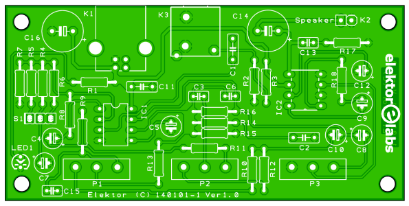
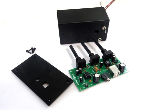
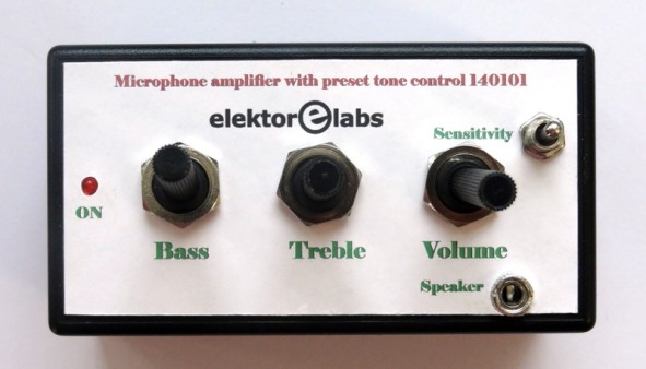
The circuit is built on the printed circuit board shown here, which was designed for compactness and low noise. The tone and volume controls P1, P2 and P3 as well as microphone input and USB supply connectors K3 and K1 are all on the PCB, avoiding wiring that would make the circuit susceptible to hum and noise. The photos illustrate a suggested method of housing the amplifier board in a compact, strong but not beer resistant, ABS case.
Component List
Resistors
R1 = 330Ω
R2 = 1MΩ
R3, R4, R9, R10, R19, R20 = 10kΩ
R5 = 470Ω
R11, R12 = 4.7kΩ
R6 = 2.2kΩ
R7 = 27kΩ
R8 = 100kΩ
R13 = 12kΩ
R14 = 3.3kΩ
R15 = 270kΩ
R16 = 2.2MΩ
R17 = 10Ω
R18 = 1.2kΩ (see text)
P1 = 100kΩ lin. potentiometer
P2 = 470kΩ lin. potentiometer
P3 = 10kΩ log. potentiometer
Capacitors
C1, C11 = 100nF 50V, X7R, 0.2’’ pitch
C2 = 2.2nF 50V, 0.1’’ pitch
C3 = 4.7nF 100V, X7R, 0.1’’ pitch
C4, C10 = 4.7μF, 50 V, 2 mm pitch, 5x11 mm
C5 = 1μF 50V, 2mm pitch
C6 = 100pF 50V, Y5P, 0.1’’ pitch
C7, C8, C9, C12 = 10μF 50V, 2mm pitch, 5x11 mm
C13, C15 = 47nF 50V, X7R, 0.1’’ pitch
C14, C16 = 220μF, 50V, 5mm pitch
Semiconductors
IC1 = TLC272 or OPA2350PA
IC2 = LM386
LED1 = LED, red, 3mm
Miscellaneous
K1 = USB type-B receptacle, right angle
K2, S1 = SIL pinheader, 0.1’’ pitch
K3 = 3.5-mm stereo jack socket, PCB mount
S1 = switch, SPDT, center-off
IC socket, DIP-8
Casing, e.g. Bud Industries CU-793, Digikey #377-1167-ND
PCB # 140101
Discussion (2 comments)