
OBD2 for Arduino
Arduino OBD2 diagnostic tester supporting Diamex DXM and Pi-OBD (AGV) modules
This project turns the Arduino into an OBD2 on-board diagnostic tester. So, the Arduino can read OBD2 vehicle data and it can read and clear emissions-related diagnostic trouble codes and inspection/maintenance readiness monitor data.
1. Supported OBD2 Features
Further features and more details can be found in my other OBD2 projects for the Elektor OBD2-Analyser NG and the OBD2 for Raspberry Pi project (chapter 4.4 OBD2 Diagnostic Services supported by HHGui/HHEmu).
2. Hardware Requirements
Parts used for the prototype:
(1) Arduino M0 and Arduino Zero should work as well, even if the Zero has 2 pins (Arduino pin 2 and 4) swapped compared to the M0/M0 Pro.
(2) Any other TFT touch shield working with 3.3V logic levels can be used if you are able to adapt the drivers coming with the shield to my software.
(3) Any other prototype board or no prototype board at all. That depends on the actual installation, see chapter 3.
(4) The old Diamex DXM OBD2 module is supported, too if you find a shop that still has it.
(5) The Pi-OBD module features two pins (5V, GND) to power the TFT display on the Pi. A selfmade Pi-OBD module 5V, GND pins to Arduino micro USB adapter could be used to power the Arduino. Do not try to power the Arduino at its 5V output pin! Without further protective diodes soldered in, this might destroy the regulator on the Arduino.
3. Hardware Preparation
The setup of the prototype is described here. Dependend on the actual installation you use for your handheld diagnostic tester (see chapter 3.4.2), your setup might differ.
3.1 Waveshare TFT Touch Shield
Solder 3 null Ohm resistors/jumpers on the backside of the TFT touch shield to route the SPI signals to Arduino digital pins 11, 12 and 13. I used short pieces of wire and soldered them on the jumper pads.
3.2 Microbot PCB Proto Shield UNO for Arduino
Solder the 4 pass-through connectors in that come with the shield.
Do not solder the ICSP header in!
The Microbot Proto shield is made for the UNO. On the UNO the ICSP header is connected to pins 11 MOSI, 12 MISO and 13 SCK.
The same wiring is found on the Proto shield. However, on the M0 Pro the ICSP header is connected to other pins 18, 21, 20 (SAMD21 PA12 MISO input, PB10 MOSI output, PB11 SCK output) and pins 11 PA16, 12 PA19, 13 PA17 (LED output) are used or free for other purposes. So, with the ICSP header soldered in, the Proto shield would at least shorten the PB11 and PA13 output port pins on the M0 Pro.
3.3 Wiring
Connect OBD2 module Tx to digital pin 0 that is used as Arduino Rx.
Connect OBD2 module Rx to digital pin 1 that is used as Arduino Tx.
For the first setup use 2.2 kOhm resistors in the Tx and Rx lines, so that no ports are destroyed, if you make a wiring error. In the error case a current of
I = U/R = 3.3V/2200Ohm = 1.5mA flows, that is below the SAMD21's limits.
Connect OBD2 module Ground to any GND pin, e.g. Arduino pin 14.
If the Pi-OBD Module is used, connect Pi-OBD Module Reset to Arduino pin 8.
If the Pi-OBD Module is used, connect Pi-OBD Module BIOS/Bootloader to GND (BIOS).
3.4 Installation of the OBD2 Module
3.4.1 Installation of the DXM OBD Module
For the DXM module that is easy. Due to its small size, it can be soldered/fixed on top of the prototype shield. The wiring can be found in chapter 2.1 of my other project here.
3.4.2 Installation of the Pi-OBD Module
As you can see in the images, I have just built a prototype using a breadboard. My Pi-OBD module was modified with a 2x13 pin stacking header for an update of the OBD2 for Raspberry Pi project. That header prevents an easy installation now.
If you want to build a real handheld diagnostic tester, there are at least three solutions.
Solution 1 (for experts only, yields the least stacking size)
You carefully have to make two changes to the Pi-OBD module.
First, desolder the pin header on the module or try to get one from Diamex without it.
Second, cut the PCB next to the two mounting holes on the right side of the PCB (orientation see ASCII art below).
Now, the Pi-OBD module can be moved in from the left until its left PCB side (that one with the two remaining mounting holes) hits the Arduino headers. With that changes, the Pi-OBD module exactly fits under the TFT touch shield and above the prototype shield.
After soldering the wiring, attach a layer of thin isolation between prototype shield and Pi-OBD module, e.g. use hot glue.
Also take care that the condensers on the Pi-OBD module do not touch the TFT touch shield, e.g. attach isolating tape on the condensers.
For additional space, the unused ICSP header on the TFT touch shield could be desoldered.
If you do not want to make that irreversible change to your new Pi-OBD module, there are two other solutions.
Solution 2 (simplest)
Simply mount the Pi-OBD module under the Arduino. My Arduino is mounted in a case. The Pi-OBD module's mounting holes placements differ from the Arduino's mounting holes placements. If 4 additional holes are drilled into the case, the Pi-OBD mounting holes can be used to screw the Pi-OBD module to the Arduino's case. If there is not enough space between Arduino and case, use plastic screws or use hot glue to fix the Pi-OBD module to the case. Then, the Pi-OBD module's mounting holes could be used to mount the whole construction in a case.
note:
If you choose this solution and come to the idea to remove the Proto board completely (if you solder the wires from/to the Pi-OBD module right to the pins on the bottom of the Arduino), you get in trouble with the SPI.
There are two ways to fix that:
1. You can fix that if you desolder the ICSP header on the TFT touch shield.
2. You can fix that if you do not solder in the 3 null Ohm resistors/jumpers on the Waveshare TFT Touch shield and if you add the define USE_ICSP_SPI to the supplied platform.local.txt file (see chapter 4, add -DUSE_ICSP_SPI to compiler.cpp.extra_flags and compiler.c.extra_flags).
Solution 3 (biggest size)
A third more complicated solution would be to use two custom made oversized prototype boards to make more space for the Pi-OBD module in between (see ASCII art below).
This needs 2 copper strip boards for the 2 prototype shields. The strips must be cut in the middle of the boards for all strips that later contain pin headers.
So that the left side of a strip connects the left female pin headers mounted on top of a board with the left male pin headers mounted under the board and the right side of a strip connects the right female pin headers mounted on top of a board with the right male pin headers mounted under the board. The backside is the solder side, if you do not use double sided strip boards with through holes.
So, this needs two sets of four Arduino female pin headers.
One set of four Arduino male pin headers.
And one set of four Arduino male pin headers with longer pins for stacking.
All headers could be made using pin strips.
4. Software Installation
The paths used here are given for an Arduino IDE 1.8.5 installation on a Win10 PC.
The file/folder names used here refer to files/folders in the HHGuiArduino.zip archive in the Downloads section.
1. copy the HHGui directory (Arduin IDE sketch folder) and all files in it to a path of your choice
2. copy the subdirectories and all files of the libraries folder to Documents\Arduino\libraries or use the Arduino IDE library manager
3. copy the file platform.local.txt to
This file sets some compiler flags needed to configure the HHOpen/HHGui software for the Arduino.
You could reduce DISPLAY_HEIGHT=96 in steps by 8 (8 pixels = one menu/list line) to get faster polling of a single OBD2 PID in the current data list menu.
DISPLAY_HEIGHT must be divisable by 8 without remainder.
DISPLAY_HEIGHT must not be less than 32.
DISPLAY_HEIGHT should not be less than 40. Otherwise some text is cut off.
DISPLAY_HEIGHT must not be greater than 128.
note: if you later compile other Arduino projects you should remove the platform.local.txt file to avoid troubles.
4. add libhhgui.a and its path to platform.txt (platform.txt is located under the same path than platform.local.txt, see above)
search for the line
note: if you later compile other Arduino projects you should undo that change in platform.txt to avoid troubles.
5. increase the Uart/Ringbuffer Rx buffer size in Ringbuffer.h
Uart/Ringbuffer uses 64 bytes of receive buffer. That is not enough to receive more than 3 OBD2 DTCs (inside the loop() function serial data is not read and copied fast enough). Change rx buffer size to 256 to fix that. Values that are not a power of 2 should be avoided, since the modulo operation to calculate the next head/tail for the ring buffer cannot be optimized by the compiler, then.
In order not to break other Arduino software, do the change in file
6. if you are using the Diamex DXM module, remove or comment out the following line in HHGui.ino
7. compile/upload the HHGui.ino sketch with Arduino IDE v1.8.5 (other versions have not been tested by me)
5. Software Description
The software base is the OBD2-Analyser NG AT90CAN128 firmware for the DXM OBD2 module. The Pi-OBD module part (AGV) of the Raspberry Pi HHGui software has been merged into it. The result is a new OBD2 handheld firmware supporting DXM and AGV OBD2 modules.
The sketch configures a custom SPI using sercom1 with pins 11 (MOSI), 12 (MISO) and 13 (SCK). The default Arduino SAMD21 SPI using sercom4 at the ICSP header is not used. Addressed SPI slave devices are the HX8347D TFT controller, the XPT2046 touch controller and the SDCard on the Waveshare 2.8inch TFT touch shield. The SDCard's chip select is just disabled. The SDCard is not used by the project.
For accessing the TFT controller a 12Mbps SPI baud rate is used.
For accessing the touch controller a 2Mbps SPI baud rate is used.
The firmware writes its display data to a 132 x 96 LCD frame buffer. The frame buffer data is scaled by 2 and centered in the 320 x 240 TFT by the TFT driver. The display orientation of the TFT originally is 240 x 320. So, the display output additionally is rotated by +90°. See TFT.cpp
For the touch panel 8bit A/D sampling of x,y-values is used. Since only 4 touch areas have to be detected (see Usage below) that is sufficient.
The hardware x,y-values are rotated by +90° as well. Furthermore, the 8bit values are scaled to match the display dimensions. See Touch.cpp
The sketch configures the timer TC3 to generate a cyclical 10ms interrupt. 10ms interval is used to debounce the touch controller's PENIRQ signal (panel touched signal). Furthermore, the firmware uses that time tick to generate own timers.
6. Usage
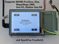
On program start four buttons UP/DOWN/ESC/OK are displayed. Actually, the button area is not just the displayed button, but the whole rectangular area surrounding that button. So, the display is divided into four rectangular areas that can be touched to control the menu accordingly.
Up/Down moves the cursor up/down in a menu/list or
increments/decrements a number +/-1 in a number field.
For the Up/Down areas long presses are recognized in some menus/lists.
Up/Down long press in a menu/list leads to a page scroll or
increments/decrements a number +/-10 in a number field.
OK selects a menu/list item or
toggles the state of a checkbox or
selects Yes for a Yes/No question or
changes to the next menu in a menu roll or
jumps one menu up if in the deepest menu.
ESC leaves a menu/list or
changes to the previous menu in a menu roll or
selects No for a Yes/No question.
1. Supported OBD2 Features
- supports up to 8 OBD2 capable ECUs
- database of 4277 descriptions for Diagnostic Trouble Codes (DTC)
- confirmed DTCs, OBD2 service 0x03
- pending DTCs, OBD2 service 0x07
- permanent DTCs, OBD2 service 0x0A
- current data, OBD2 service 0x01
- freeze frame data, OBD2 service 0x02
- supported PIDs for service 0x01 and 0x02: 0x00 to 0x64, 0x70, 0x80, 0x84, 0x8D, 0x8E, 0xA0, 0xC0, 0xE0
- dynamic supported PIDs for OBD2 service 0x02 (each DTC that caused freeze frame storage can have its own supported PIDs)
- evaluation and display of location of oxygen sensors, OBD2 service 0x01 and 0x02, PID 0x13 or 0x1D (this affects displayed bank/oxygen sensor indices of some PIDs)
- evaluation of tester configuration bytes, OBD2 service 0x01 and 0x02, PID 0x4F and PID 0x50 (this affects displayed maximum values and resolution of some PIDs)
- Inspection/Maintenance Readiness Code / OBD2 monitor status since DTCs cleared, OBD2 service 0x01, PID 0x01
- OBD2 monitor status of the current driving cycle, OBD2 service 0x01, PID 0x41
- Vehicle Identification Numer (VIN), OBD2 service 0x09, infotype 0x02
- Calibration IDs (CALIDs), OBD2 Service 0x09, infotype 0x04
- Calibration Verification Numbers (CVNs), OBD2 service 0x09, infotype 0x06
- ECU name, OBD2 service 0x09, infotype 0x0A
- in-use performance tracking counters for spark ignition engines and compression ignition engines prior MY2010, OBD2 service 0x09, infotype 0x08
- in-use performance tracking counters for compression ignition engines for MY2010 and beyond, OBD2 service 0x09, infotype 0x0B
Further features and more details can be found in my other OBD2 projects for the Elektor OBD2-Analyser NG and the OBD2 for Raspberry Pi project (chapter 4.4 OBD2 Diagnostic Services supported by HHGui/HHEmu).
2. Hardware Requirements
Parts used for the prototype:
- Arduino M0 Pro
- Waveshare 2.8inch TFT touch shield
- Microbot PCB Proto Shield UNO for Arduino (optional)
- Diamex Pi-OBD module + OBD2 cable
- 12V vehicle socket to USB adapter to power the Arduino via USB
(1) Arduino M0 and Arduino Zero should work as well, even if the Zero has 2 pins (Arduino pin 2 and 4) swapped compared to the M0/M0 Pro.
(2) Any other TFT touch shield working with 3.3V logic levels can be used if you are able to adapt the drivers coming with the shield to my software.
(3) Any other prototype board or no prototype board at all. That depends on the actual installation, see chapter 3.
(4) The old Diamex DXM OBD2 module is supported, too if you find a shop that still has it.
(5) The Pi-OBD module features two pins (5V, GND) to power the TFT display on the Pi. A selfmade Pi-OBD module 5V, GND pins to Arduino micro USB adapter could be used to power the Arduino. Do not try to power the Arduino at its 5V output pin! Without further protective diodes soldered in, this might destroy the regulator on the Arduino.
3. Hardware Preparation
The setup of the prototype is described here. Dependend on the actual installation you use for your handheld diagnostic tester (see chapter 3.4.2), your setup might differ.
3.1 Waveshare TFT Touch Shield
Solder 3 null Ohm resistors/jumpers on the backside of the TFT touch shield to route the SPI signals to Arduino digital pins 11, 12 and 13. I used short pieces of wire and soldered them on the jumper pads.
3.2 Microbot PCB Proto Shield UNO for Arduino
Solder the 4 pass-through connectors in that come with the shield.
Do not solder the ICSP header in!
The Microbot Proto shield is made for the UNO. On the UNO the ICSP header is connected to pins 11 MOSI, 12 MISO and 13 SCK.
The same wiring is found on the Proto shield. However, on the M0 Pro the ICSP header is connected to other pins 18, 21, 20 (SAMD21 PA12 MISO input, PB10 MOSI output, PB11 SCK output) and pins 11 PA16, 12 PA19, 13 PA17 (LED output) are used or free for other purposes. So, with the ICSP header soldered in, the Proto shield would at least shorten the PB11 and PA13 output port pins on the M0 Pro.
3.3 Wiring
Connect OBD2 module Tx to digital pin 0 that is used as Arduino Rx.
Connect OBD2 module Rx to digital pin 1 that is used as Arduino Tx.
For the first setup use 2.2 kOhm resistors in the Tx and Rx lines, so that no ports are destroyed, if you make a wiring error. In the error case a current of
I = U/R = 3.3V/2200Ohm = 1.5mA flows, that is below the SAMD21's limits.
Connect OBD2 module Ground to any GND pin, e.g. Arduino pin 14.
If the Pi-OBD Module is used, connect Pi-OBD Module Reset to Arduino pin 8.
If the Pi-OBD Module is used, connect Pi-OBD Module BIOS/Bootloader to GND (BIOS).
3.4 Installation of the OBD2 Module
3.4.1 Installation of the DXM OBD Module
For the DXM module that is easy. Due to its small size, it can be soldered/fixed on top of the prototype shield. The wiring can be found in chapter 2.1 of my other project here.
3.4.2 Installation of the Pi-OBD Module
As you can see in the images, I have just built a prototype using a breadboard. My Pi-OBD module was modified with a 2x13 pin stacking header for an update of the OBD2 for Raspberry Pi project. That header prevents an easy installation now.
If you want to build a real handheld diagnostic tester, there are at least three solutions.
Solution 1 (for experts only, yields the least stacking size)
You carefully have to make two changes to the Pi-OBD module.
First, desolder the pin header on the module or try to get one from Diamex without it.
Second, cut the PCB next to the two mounting holes on the right side of the PCB (orientation see ASCII art below).
 -------              -
|o      |            |o|
|       |            | | <-- cut here, the 5V/GND pin header should stay
|       |          --  |
|       |         |    |
|       |         |    |
|        ---------     |
|                      |
|                      |
|                      |
|          ----------  | <-- cut here
|o        |          |o|
 ---------            -
Now, the Pi-OBD module can be moved in from the left until its left PCB side (that one with the two remaining mounting holes) hits the Arduino headers. With that changes, the Pi-OBD module exactly fits under the TFT touch shield and above the prototype shield.
After soldering the wiring, attach a layer of thin isolation between prototype shield and Pi-OBD module, e.g. use hot glue.
Also take care that the condensers on the Pi-OBD module do not touch the TFT touch shield, e.g. attach isolating tape on the condensers.
For additional space, the unused ICSP header on the TFT touch shield could be desoldered.
If you do not want to make that irreversible change to your new Pi-OBD module, there are two other solutions.
Solution 2 (simplest)
Simply mount the Pi-OBD module under the Arduino. My Arduino is mounted in a case. The Pi-OBD module's mounting holes placements differ from the Arduino's mounting holes placements. If 4 additional holes are drilled into the case, the Pi-OBD mounting holes can be used to screw the Pi-OBD module to the Arduino's case. If there is not enough space between Arduino and case, use plastic screws or use hot glue to fix the Pi-OBD module to the case. Then, the Pi-OBD module's mounting holes could be used to mount the whole construction in a case.
note:
If you choose this solution and come to the idea to remove the Proto board completely (if you solder the wires from/to the Pi-OBD module right to the pins on the bottom of the Arduino), you get in trouble with the SPI.
There are two ways to fix that:
1. You can fix that if you desolder the ICSP header on the TFT touch shield.
2. You can fix that if you do not solder in the 3 null Ohm resistors/jumpers on the Waveshare TFT Touch shield and if you add the define USE_ICSP_SPI to the supplied platform.local.txt file (see chapter 4, add -DUSE_ICSP_SPI to compiler.cpp.extra_flags and compiler.c.extra_flags).
Solution 3 (biggest size)
A third more complicated solution would be to use two custom made oversized prototype boards to make more space for the Pi-OBD module in between (see ASCII art below).
This needs 2 copper strip boards for the 2 prototype shields. The strips must be cut in the middle of the boards for all strips that later contain pin headers.
So that the left side of a strip connects the left female pin headers mounted on top of a board with the left male pin headers mounted under the board and the right side of a strip connects the right female pin headers mounted on top of a board with the right male pin headers mounted under the board. The backside is the solder side, if you do not use double sided strip boards with through holes.
So, this needs two sets of four Arduino female pin headers.
One set of four Arduino male pin headers.
And one set of four Arduino male pin headers with longer pins for stacking.
All headers could be made using pin strips.
------------- TFT touch shield
| | <- TFT touch shield male pin headers
I I <- female pin headers
--------------------- custom prototype shield 1
| | <- male pin headers with stacking height
| Pi-OBD module |
I --------------- I <- female pin headers
--------------------- custom prototype shield 2
| | <- male pin headers
I I <- Arduino female pin headers
------------- Arduino
4. Software Installation
The paths used here are given for an Arduino IDE 1.8.5 installation on a Win10 PC.
The file/folder names used here refer to files/folders in the HHGuiArduino.zip archive in the Downloads section.
1. copy the HHGui directory (Arduin IDE sketch folder) and all files in it to a path of your choice
2. copy the subdirectories and all files of the libraries folder to Documents\Arduino\libraries or use the Arduino IDE library manager
3. copy the file platform.local.txt to
C:\Users\YOUR USER NAME\AppData\Local\Arduino15\packages\arduino\hardware\samd\1.6.16\
The numbers in the path might change with different Arduino IDE and SAMD core versions.This file sets some compiler flags needed to configure the HHOpen/HHGui software for the Arduino.
You could reduce DISPLAY_HEIGHT=96 in steps by 8 (8 pixels = one menu/list line) to get faster polling of a single OBD2 PID in the current data list menu.
DISPLAY_HEIGHT must be divisable by 8 without remainder.
DISPLAY_HEIGHT must not be less than 32.
DISPLAY_HEIGHT should not be less than 40. Otherwise some text is cut off.
DISPLAY_HEIGHT must not be greater than 128.
note: if you later compile other Arduino projects you should remove the platform.local.txt file to avoid troubles.
4. add libhhgui.a and its path to platform.txt (platform.txt is located under the same path than platform.local.txt, see above)
search for the line
compiler.arm.cmsis.ldflags="-L{runtime.tools.CMSIS-4.5.0.path}/CMSIS/Lib/GCC/" -larm_cortexM0l_math
and change it to
compiler.arm.cmsis.ldflags="-L{runtime.tools.CMSIS-4.5.0.path}/CMSIS/Lib/GCC/" -larm_cortexM0l_math "-LYOUR PATH\HHGui" -lhhgui
change YOUR PATH\HHGui to the path you used for the HHGui folder in step 1note: if you later compile other Arduino projects you should undo that change in platform.txt to avoid troubles.
5. increase the Uart/Ringbuffer Rx buffer size in Ringbuffer.h
Uart/Ringbuffer uses 64 bytes of receive buffer. That is not enough to receive more than 3 OBD2 DTCs (inside the loop() function serial data is not read and copied fast enough). Change rx buffer size to 256 to fix that. Values that are not a power of 2 should be avoided, since the modulo operation to calculate the next head/tail for the ring buffer cannot be optimized by the compiler, then.
In order not to break other Arduino software, do the change in file
C:\Users\YOUR USER NAME\AppData\Local\Arduino15\packages\arduino\hardware\samd\1.6.16\cores\arduino\RingBuffer.h
like this:
#ifdef HHOPEN_ARDUINO
#define SERIAL_BUFFER_SIZE 256
#else
#define SERIAL_BUFFER_SIZE 64
#endif
6. if you are using the Diamex DXM module, remove or comment out the following line in HHGui.ino
#define HAS_AGV 1
leave that line as is if you are using the Diamex Pi-OBD module7. compile/upload the HHGui.ino sketch with Arduino IDE v1.8.5 (other versions have not been tested by me)
5. Software Description
The software base is the OBD2-Analyser NG AT90CAN128 firmware for the DXM OBD2 module. The Pi-OBD module part (AGV) of the Raspberry Pi HHGui software has been merged into it. The result is a new OBD2 handheld firmware supporting DXM and AGV OBD2 modules.
The sketch configures a custom SPI using sercom1 with pins 11 (MOSI), 12 (MISO) and 13 (SCK). The default Arduino SAMD21 SPI using sercom4 at the ICSP header is not used. Addressed SPI slave devices are the HX8347D TFT controller, the XPT2046 touch controller and the SDCard on the Waveshare 2.8inch TFT touch shield. The SDCard's chip select is just disabled. The SDCard is not used by the project.
For accessing the TFT controller a 12Mbps SPI baud rate is used.
For accessing the touch controller a 2Mbps SPI baud rate is used.
The firmware writes its display data to a 132 x 96 LCD frame buffer. The frame buffer data is scaled by 2 and centered in the 320 x 240 TFT by the TFT driver. The display orientation of the TFT originally is 240 x 320. So, the display output additionally is rotated by +90°. See TFT.cpp
For the touch panel 8bit A/D sampling of x,y-values is used. Since only 4 touch areas have to be detected (see Usage below) that is sufficient.
The hardware x,y-values are rotated by +90° as well. Furthermore, the 8bit values are scaled to match the display dimensions. See Touch.cpp
The sketch configures the timer TC3 to generate a cyclical 10ms interrupt. 10ms interval is used to debounce the touch controller's PENIRQ signal (panel touched signal). Furthermore, the firmware uses that time tick to generate own timers.
6. Usage
On program start four buttons UP/DOWN/ESC/OK are displayed. Actually, the button area is not just the displayed button, but the whole rectangular area surrounding that button. So, the display is divided into four rectangular areas that can be touched to control the menu accordingly.
  ---------------------------
 |             |             |
 |     UP      |     ESC     |
 |             |             |
 |---------------------------|
 |             |             |
 |    DOWN     |     OK      |
 |             |             |
  ---------------------------
Up/Down moves the cursor up/down in a menu/list or
increments/decrements a number +/-1 in a number field.
For the Up/Down areas long presses are recognized in some menus/lists.
Up/Down long press in a menu/list leads to a page scroll or
increments/decrements a number +/-10 in a number field.
OK selects a menu/list item or
toggles the state of a checkbox or
selects Yes for a Yes/No question or
changes to the next menu in a menu roll or
jumps one menu up if in the deepest menu.
ESC leaves a menu/list or
changes to the previous menu in a menu roll or
selects No for a Yes/No question.
Updates from the author