
Soft Start for Amplifiers
on
In the case of power supplies having a power transformer, the peak inrush current is caused by the magnetic core saturation, while in the case of switching power supplies (SMPSU) it is caused by the discharged DC link capacitor. The inrush current is very high and taxes many parts. It is therefore not surprising that devices and/or their power circuits almost always break down at the time of switching on — just like the death of an old-fashioned (and now banned) incandescent lamp the instant you flip the switch.

Manufacturers of electrical and electronic equipment (and readers of Elektor Mag) are all too familiar with this phenomenon. And the remedy is also known — somehow the inrush current must be limited.
Power to the power transformer!
The higher the induction in the iron core of the transformer, the smaller the air gap, and the smaller the copper losses, the higher the current surge. Contrary to what you may think, this peak current is the highest when the mains voltage is switched on exactly at the time of the zero crossing.
The reason is revealed by a little maths. Once switched on and all switch-on symptoms over, the phase shift between the mains voltage and the magnetic flux is 90°, as described by

This equation is derived from Faraday's Law. It follows that:

The magnetic flux thus reaches its negative maximum at the zero crossing of the mains voltage. In continuous operation of the transformer, the constant C equals zero.
However, this is not the case at the time of switching on, because the magnetic flux must start at zero (provided that the iron core does not have residual magnetism). So when we switch on the transformer at time t = 0, the starting condition of the magnetic flux is defined by the constant C, and that constant itself depends on
- the value and polarity of the iron core's residual magnetism;
- the phase of the applied AC voltage;
- the properties of the core material.
In summary, we can write:

Assuming that φrest = 0, then we find:
- when we switch on the mains voltage at the moment that it is maximal: φ = φmax;
- but when we switch on the zero transit: φ = 2-φmax.
This double size magnetic flux sends the transformer core in (magnetic) saturation, so that the inductance of the coil drops almost to zero, leaving the current to be limited only by the ohmic resistance of the winding and the power cord.
The switch-on current peak lasts for a maximum of 10 ms. In practice, we can expect a time span of 3–6 ms because the core does not go into saturation abruptly but takes some time to do so. However, we should not forget that it takes about 4–10 periods of the mains voltage before the magnetic flux — and with it the coil current — have assumed their ‘stationary’ values.
Possible solutions
In order to avoid the problem of large inrush current surges, we could somehow try to switch on the transformer only when the mains voltage has reached its peak value — then we avoid the wretched inrush peak.
That by itself is correct but for it to function properly, the residual magnetism of the core at the switch-on time must always be zero, and that is something that cannot be guaranteed in practice. However, there are circuits that measure this residual magnetism and can operate without current limiting resistors. However, these circuits are quite complicated.
Another possibility is to dimension the transformer in such a way that it does not reach saturation so quickly. This works, but leads to higher costs and greater electrical losses, while also increasing the size of the transformer, which in most cases will be undesirable.
For practical reasons we leave the inrush current peak for what it is. After all, it doesn't damage the transformer due to its short duration — when we're not talking about extreme powers here. We solve the problem through inrush current limiting. As we will see, the process can be carried out both passively and actively.
 Table 1 gives an impression of the inrush currents that occur when transformers are more or less heavy. Clearly some form of inrush current limitating is necessary from powers of about 300 VA onwards in order to prevent a fuse exchange circus to put it that way.
Passive inrush current limiting
For passive inrush current limiting, ‘fat’ resistors or thermistors are usually applied. Thermistors are simply resistors whose resistance depends on the temperature. We all know them as NTC and PTC resistors.
When it comes to the limiting of inrush currents, only NTC resistors are considered, i.e. resistors with a negative temperature coefficient. They have a higher resistance in the cold state than in the warm state.
In the case of a purely passive inrush current limiting, the thermistor is in series with the load. When switched off (i.e. at room temperature), the resistance is such that the inrush current is limited to a safe, manageable value. As a result of the current passing through the thermistor, the device heats up (it dissipates power) and its resistance decreases to ultimately no more than a few ohms and the current reaches its nominal (stationary) value. This solution with thermistors is generally considered to be reliable and cheap.
Important parameters in the selection of the thermistor are the initial resistance (in the ‘cold’ state) and the current carrying rating. The value of the resistor should be chosen to limit the current flowing through the load to a value which does not yet make the fuse work (and which cannot damage the load).
In the following, we assume a 500-VA power transformer for dimensioning, which is fused with Ismax = 10 A by a device fuse present in the device in question.
We calculate the cold resistance of the thermistor from:

The cold resistance of our thermistor should be 30 Ω. Now we have to calculate the current flowing through the thermistor in stationary (continuous) operation (we assume that the transformer is under maximum load):

For our 500-VA transformer we arrive at 2.2 A.
Finally, we need to estimate the maximum energy the thermistor has to convert into heat immediately after being switched on. Assuming that the switch-on pulse is approximately rectangular-shaped, then the product 'power times time' corresponds to the amount of energy. We find:
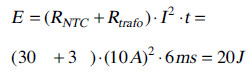
The data sheet of the TDK S236 series of thermocouples (see Figure 1) does not mention this maximum allowable energy as such. Instead, we find a maximum allowable load capacitance Ctest that can be connected to the current limiting thermistor. In the case of switching power supplies, the value of the DC link capacitor may be used for this purpose. We then calculate:

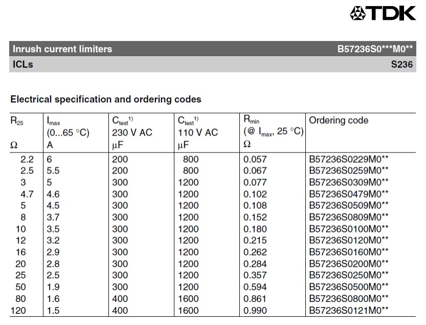
The load rating of a single thermistor is too low; we have to switch to a 'beefier' one or connect two thermistors in series (note: thermistors must not be connected in parallel). We have chosen for the latter option: two 16-Ω thermistors in series.
Disadvantages
Although passive inrush current limiting is often found in consumer electronics, there are some disadvantages to it.
In the first place: although the warm resistance of the thermistor is only 1/20 to 1/10th of the cold resistance, it still dissipates a considerable amount of power, in our case at least about 8 W, and this is of course undesirable for environmental reasons alone. In addition, the thermistor heats up: at nominal load, its temperature increases to (in our case) no less than 150 °C.
Consequently the device in question must not be switched on again immediately after it’s been switched off: The thermistor quickly takes a minute or more to cool down to such an extent that it can once again act as a limiter.
Parts and soldering joints in the immediate vicinity are also affected by this heat buildup; especially plastic parts must be mounted at a sufficient distance from the thermistor(s).
A relay provides a solution
In Figure 2 we have outlined a commonly used (active) solution to the power dissipation problem. We see here a power supply with upstream thermistor. A relay contact that is closed shortly after switching on is connected in parallel with the thermistor. The thermistor is then bridged so that no more power is dissipated in it. Of course, some power is lost in the relay (about 1 W) but that is much less than the minimum 8 W for the version without the relay.
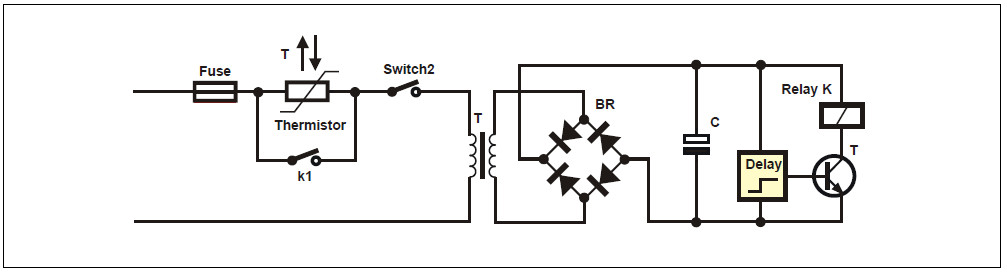
The switch-on electronics are often powered by a small auxiliary transformer. This disconnects the switch-on electronics from the device power supply, so that even a short power failure leads to a safe reset of the switch-on electronics. Another advantage of this design is that the power switch of the device can be replaced by a low-voltage switch through a second relay.
And now, in practice
After all these (hopefully interesting) theoretical considerations it’s time to roll up our sleeves. The soft start circuit in this article was originally designed for an audio power amplifier with a switching power supply. Admittedly, opinions on the use of switching power supplies in audio amplifiers are divided, but a. SMPSU has some important advantages over a classic linear power supply with a toroidal transformer. On the one hand, the efficiency is higher than with a linear power supply, and on the other hand, the smaller dimensions permit building smaller and lighter power amplifiers, which can also easily be built into a loudspeaker case Another advantage is that the output voltage is controlled, ensuring a safe maximum value of the output voltage is not exceeded or undershot, even with varying loads. And if the topology of the controller is chosen correctly, it is possible to obtain an extremely 'clean' supply voltage.
Special switching power supplies are now being developed for audio applications.
Block diagram
All considerations eventually led to a softstart unit with microcontroller supervision. A microcontroller offers an excellent opportunity to realise a number of expansions without too much hardware fuss, such as an audio-triggered autostart function which turns off the amplifier when no audio signal is present for a while, and which automatically switches on the amplifier when an audio signal is available. There is also an infrared receiver allowing the volume to be adjusted (via a motor potentiometer). Figure 3 shows the block diagram of the final circuit.
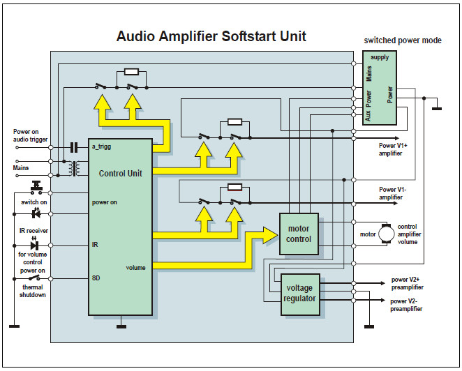
The heart of the circuit is formed by the microcontroller — and although it is prominently present, in practice a relatively modest ATTiny44 proved enough. The mains voltage comes from the left inside and powers the softstart unit through its own small transformer. At the same time this mains voltage is conveyed, via a relay/thermistor circuit, to the actual (switching) power supply of the amplifier shown in the upper right-hand corner.
This provides the power supply voltages V1+ and V1– for the amplifier which are additionally protected via relay/thermistor combinations. From this the voltages V2+ and V2– are derived in a conventional way, ready for powering a preamplifier. In addition, the power supply also provides an auxiliary voltage that’s used to control the motor potentiometer.
The detailed schematic
...is pictured in Figure 4. The various components of the block diagram are easy to recognize. The top left hand area(K9, K1 and K11) is the power part. The mains voltage for the power supply of the softstart unit itself is connected to K1. The switched supply for the switched-mode power supply arrives via K11.
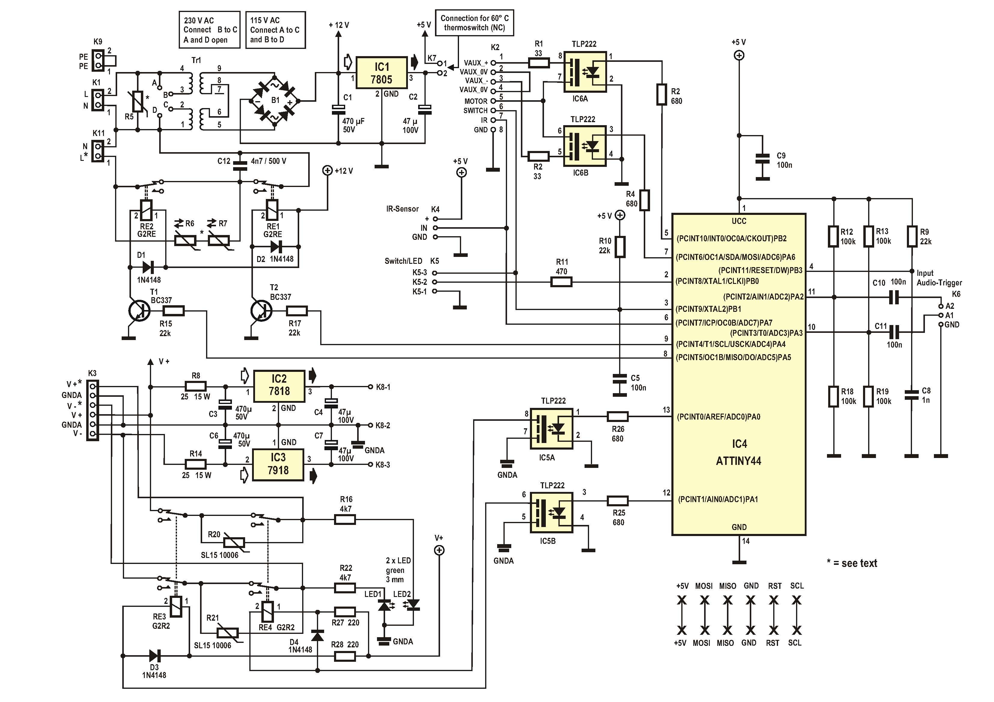
K9 has no real function but only serves to comfortably loop through any protective earth (PE) line.
The power supply voltages for the amplifier provided by the switching power supply arrive at K3 as V+, GNDA and V–. The well-known linear regulator pair 7818/7918 (IC2 and IC3) produces an extra stabilized supply voltage of ±18 V for a preamplifier if present. V+ and V– pass through the relays R3 and R4 to the amplifier as V+* and V–*. The two green LEDs serve as status indicators.
The amplifier power supply used by the author also provides an auxiliary voltage VAUX to control the motor of the motor potentiometer for volume control. This voltage comes in at connector K2 and is transferred to the motor by the two semiconductor relays in IC6 as needed.
The manual on/off switch (push button) is connected to K5 together with an on/off LED. The IR receiver is connected to K4.
The IR receiver
The option to connect an IR receiver and control the amplifier remotely is of course very attractive. However, it turned out that there were a couple of pitfalls. The main problem is of course which remote controls (i.e.: which data protocols) the software should be compatible with. There are numerous IR remote controls in circulation, as well as numerous variations on the IR protocol.
For this reason, the author abandoned the idea of using a specific remote control and tuning the software accordingly. Instead, the software for the softstart unit has been designed so that it can — within certain limits — learn some commands from commonly used IR remote controls.
Celebrating the motto "keep it simple", the software supports no more than three commands, which in practice are sufficient to operate an audio power amplifier:
- on/off
- volume +
- volume –

A commercial IR receiver is used here as its cost defies any attempt at home construction. In addition, these modules (Figure 5) decode the received IR signal and provide their output with a ready-to-use demodulated signal that can be fed directly to the microcontroller. Here you will find a lot of useful information on this subject.
Finally, a thermostat module can be connected to connector K7 (if desired) to switch off the amplifier when the temperature in the casing exceeds about 60 °C).
The software
The software is written in assembler for an ATTiny44, using ATMEL Studio 7. Thanks to the extensive hardware functionality of the ATTiny44 and the spacious memory, a compact solution was found for the softstart unit, especially when we take into account its possibilities. For the record: we don't go into the code in detail here; if you like it, you can download the firmware and find out for yourself.
One of the most interesting features of the ATTiny is the so-called 'Capture Function' which we embraced for IR reception. With this function, the µC loads a copy of the counter position of the 16-bit timer to the Capture input pin in the so-called capture register, on every edge of the signal. In this way an extremely accurate (order of magnitude: microseconds) time measurement is possible.
Figure 6 shows the state diagram of the software. The microcontroller controls a total of four relays (K1–K4 in the image, RE1–RE4 in the diagram) for the switch-on process. In Figure 6 'button' is the pushbutton for manual switch-off (see below). The process is sequential.
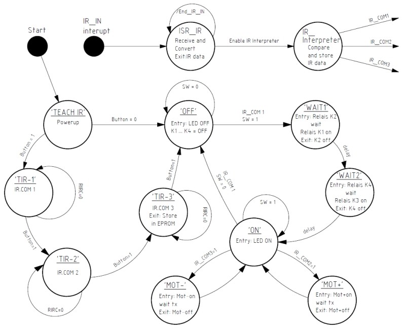
First, relay RE2 activates thermistor R6/R7. After a short delay, the circuit is closed by relay RE1 and after the delay 'wait1', relay RE2 is switched off again so that the thermistor is bypassed. The switching power supply for the amplifier is now directly connected to the mains but is currently unloaded.
Now the supply voltage is fed to the amplifier. First, relay RE4 connects both thermistors R20 and R21 into the positive and negative power lines of the amplifier. This is done to load the 'fat' reservoir electrolytic of the amplifier in a current-limited fashion. Doing so protects the components concerned and prevents the SMPSU from getting stuck in a short-circuit loop. After another short delay, the supply voltage is transferred 'hard' by relay RE3.
Teaching commands
The 'learning mode' for the IR remote control is activated by holding down the ID key while plugging in the softstart unit. The softstart unit remembers the IR signal and stores it in EEPROM. The LED indicates successful reception. To learn the second command, press the pushbutton again; the same for the third command.
In total three commands can be stored. The first command is the on/off command, the second the volume-up command ('louder’) and the third, the volume-down command ('softer').
Final notes on the hardware
The hardware has an autostart function. As soon as an audio voltage is applied to the differential input of the microcontroller (pins 10 and 11), the amplifier switches itself on as described above. The switching threshold is approximately 20 mV. If no input signal is detected for a period of about 5 minutes, the amplifier switches itself off again. The standby consumption of the circuit is less than 1 W in this case. The audio signal proper is connected to connector K6.
The author uses a type SMPS300RE switching power supply from Connex Electronics. This provides an extra auxiliary voltage of ±12 V, which is used to control the motor potentiometer of the amplifier. For this purpose, the two bidirectional MOS relays in IC6 convey either the positive or the negative auxiliary voltage to the motor. The current is limited by resistors R1 and R2. Each volume command switches the motor on for 500 ms in the desired direction of rotation.
When the amplifier is turned on, it can be turned off by pressing the pushbutton.
Construction
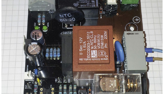
A (double-sided) PCB was designed for the softstart unit — see Figure 7. And you will no doubt be pleased that this is a real 'old-fashioned' PCB with through-hole components only.
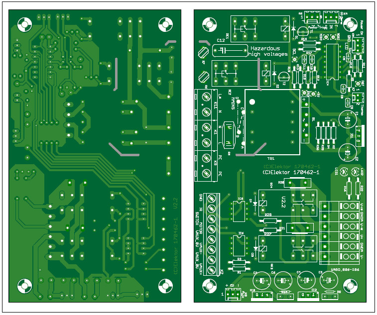
We have somewhat 'internationalised' the author's original design — i.e. made it suitable for both 230 VAC and 115 VAC mains (US: ‘line’) voltage. This means that you must be careful when selecting and assembling some parts.
- First, the transformer. That's a type with two primary windings. For 230 VAC, points B and C must be connected on the PCB (use insulated wire!) while points A and D remain open. For 115 VAC use, point A must be connected to point C and point B to point D (again: use insulated wire!).
- Next, varistor R5. Its value follows the AC line voltage: 230 V or 115 V. Take a good look at the parts list here!
- Then, thermistors R6 and R7. These have the same value (see parts list), but for 230 VAC both thermistors must be mounted, while for 115 VAC only R6 is mounted and R7 is replaced by an (insulated!) wire jumper.
Finally, connector K3 deserves some attention. The author has used a Wago PCB, which is adequate but may be difficult to obtain outside of Germany. Instead, you can also use a 6-way, 0.2 inch pitch PCB screw terminal block, e.g. the Multicomp type from the Components List. Note: if you choose the Wago PCB terminal, you should also order the corresponding Wago 6-pin header!
 The PCB is of course available in the Elektor Store and the same goes for the programmed ATTiny44 (see the box: @ www.elektor.com). However, if you want to program your own controller, feel free to do so. The firmware can be downloaded from the project page with this article (free of charge, as you would expect from us). You can then program the ATTiny44 with an AVRISP, which is connected to the corresponding PCB pins on the PCB (5V, MOSI, MISO, GND, RST and SCL).
Last but not least: parts of the PCB carry life-threatening voltages; therefore, build in the whole project in a touch-safe manner! All that remains for us to do is to wish you lots fun building the softstart and hope you can enjoy long and undisturbed listening.
(170462-03)
Want more great Elektor content like this?
--> Take out an Elektor membership today and never miss an article, project, or tutorial.
Discussion (2 comments)