


E-ink voltmeter multichannel for PIC uC:
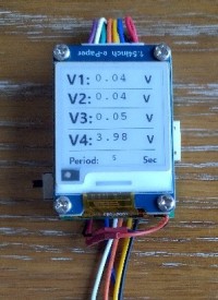
For another project under development, I have to check several voltages in parallel (4 here). As it must be put on a bike, I wanted very low consumption. So, E-Ink display was good option, except that I could not find any good library for PIC uC.
E-Ink display is very attractive for low consumption project, as long as refresh time is not high.
For another under going project (based on harvest energy), I wanted to have multichannel voltmeter, capable to measure from 10mv to 10V and at a max frequency of display 1 sec.
I wanted to use as usual PIC uC, 18F26K42 in my case (I had a previous project and board on this uC) as it can be low consumption.
Looking a lot around, I could not find appropriate library for any kind of E-Ink. So, I have to spend weeks and months to develop one.
For the E-Ink, I use a Waveshare 1.54'' display, V2.1 version (I started with the V1 version but it is different driver).
I was quite complicated to manage the setup of the display, the full refresh and partial refresh.
At the end, I have a multichannel (4) device which is checking the voltage every 5 seconds and change the display (partial refresh) if the value is different.
A button on the module will change the period of checking the voltage channel. The period is written on the bottom of the screen.
Like for many E-Ink display, partial refresh cannot be done endless. Every 100 refresh per example, a full refresh is necessary. This is implemented as well.
On the picture, the mock up with the display, the control board of it (with the PIC) and 2 harvest small PCBs which are charging a supercapacitor. The device monitor the 2 harvests modules and the battery voltage. I put it on a carton box and It can be fix on the handle bar of my bike for tests...
I plan to put it on a PCB, same size than the display module which can be mount on its back.
On the schematic, we can see that the 4 input voltage are measured from the A/D of the CPU. The voltage reference is inside the CPU (FVR) and fixed to 2.048v. The input voltage are divided by fix resistor (better 1%) 100k/300k.
There is also a simple LiPo battery charger on the schematic.
The PCB is plan to be put on the bottom of the display.
The CPU is powered by a fix regulator 3v, LDO.
Laurent
For another under going project (based on harvest energy), I wanted to have multichannel voltmeter, capable to measure from 10mv to 10V and at a max frequency of display 1 sec.
I wanted to use as usual PIC uC, 18F26K42 in my case (I had a previous project and board on this uC) as it can be low consumption.
Looking a lot around, I could not find appropriate library for any kind of E-Ink. So, I have to spend weeks and months to develop one.
For the E-Ink, I use a Waveshare 1.54'' display, V2.1 version (I started with the V1 version but it is different driver).
I was quite complicated to manage the setup of the display, the full refresh and partial refresh.
At the end, I have a multichannel (4) device which is checking the voltage every 5 seconds and change the display (partial refresh) if the value is different.
A button on the module will change the period of checking the voltage channel. The period is written on the bottom of the screen.
Like for many E-Ink display, partial refresh cannot be done endless. Every 100 refresh per example, a full refresh is necessary. This is implemented as well.
On the picture, the mock up with the display, the control board of it (with the PIC) and 2 harvest small PCBs which are charging a supercapacitor. The device monitor the 2 harvests modules and the battery voltage. I put it on a carton box and It can be fix on the handle bar of my bike for tests...
I plan to put it on a PCB, same size than the display module which can be mount on its back.
On the schematic, we can see that the 4 input voltage are measured from the A/D of the CPU. The voltage reference is inside the CPU (FVR) and fixed to 2.048v. The input voltage are divided by fix resistor (better 1%) 100k/300k.
There is also a simple LiPo battery charger on the schematic.
The PCB is plan to be put on the bottom of the display.
The CPU is powered by a fix regulator 3v, LDO.
Laurent
Want to build a project?
Bring your design to life with the Elektor PCB Service, powered by Eurocircuits. Upload the project files and order professionally manufactured PCBs or assembled boards through a proven European production platform.
Supporting KiCad, Eagle, Gerber, and ODB++ formats, the service is suitable for everything from prototypes and validation builds to series production and volume manufacturing.
Made in Europe. Fast. Reliable. Professional.
Discussion (0 comments)