Programming the Arduino in BASIC - Using RTC Part. 4
With this project, I conclude my presentation of Basic for Arduino. Unless you have any further requests, I will take a break. Please let me know if you enjoyed using Great Cow Basic. Best regards
Presentation of the DS1307 RTC module (Real Time Clock)
The DS1307 RTC (Real Time Clock) module is used to provide an accurate clock function in electronic projects. It uses an internal clock based on a quartz oscillator to maintain the time and date. It has registers for storing the time, date, alarm, and other time-related information. A backup battery keeps the time and date even in the event of a power failure. It communicates with the Arduino microcontroller via the I2C bus.
This tutorial will help you get started and understand how to use RTC (Real Time Clock) clocks.
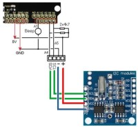
There are many ready-to-use modules available. The module I use has two circuits: - a DS1307 chip, - an AT24C32 chip (EEPROM memory). The internal memory of the DS1307 is divided into registers (1-byte memory) that can be accessed either directly or sequentially.
The simplified organization is as follows :
Registre Adresse Secondes (0 à 59) 00 Minutes (0 à 59) 01 Heures (0 à 23) 02 Jour de la semaine (1 à 7) 03 (dimanche : 1, lundi : 2, mardi : 3 etc…) Date (1 à 31) 04 Mois (1 à 12) 05 Année (00 à 99) 06
All registers are encoded in BCD (Binary Coded Decimal), not pure binary. During direct access, the master can request a specific register from the component, so it must indicate the address of this register each time it communicates via I2C.
Sequential access allows you to take advantage of the auto-incrementing internal address counter, which allows you to read several registers at once... All data read on the real-time module is encoded in BCD (binary-coded decimal) format. In BCD format, numbers are represented by decimal digits, each of which is encoded using 4 bits.
The following examples illustrate this encoding : Up to 9, the conversion to binary is standard:
Beyond 9, each number is broken down into two 4-bit packets : Number bits valeurs 10 0001 0000 or 0001 0000(binaire) = 16(décimal)
11 0001 0001 or 0001 0001(binaire) = 17(décimal)
Another exemple : 29 0010 1001 or 0010 1001(binaire) = 41(décimal)
This method allows for correspondence with ASCII character codes.
Setting the time on the DS1307 module When using the module for the first time, it will certainly need to be set to the correct time. Although it is possible to use I2C commands, using the ds1307.h library greatly simplifies things. The Test1_RTC_reglage.gcb program, which is dedicated solely to setting the time, will allow you to test future programs. The specific command is very easy to use :
Don't forget to download the program at the exact time specified in your configuration.
Reading the DS1307 registers The organizational chart makes it easy to understand how to retrieve the records : The Test2_RTC_BCD.gcb program is exactly the Basic implementation of the flowchart.
The Test2_RTC_BCD.gcb program does not use any specific libraries and has a few surprises in store.
It is 5:57 p.m. and 35 seconds. Sunday, November 2, 2025.
The LCD display shows : Correct display therefore requires conversion from a BCD value to a decimal value.
To convert the variable Value encoded in DCB to a decimal number, simply separate the groups of 4 bits, convert them to decimal values and recombine the digits.
The conversion calculation is: DecimalValue = ((BCDValue/16)x10) + (BCDValue Mod 16)
(BCDValue/16)x10: the tens digit is retrieved by shifting the 4 bits to the left. BCDValue Mod 16: the modulo is the remainder of a division : we retrieve the units digit.
Note: do not try to do the calculation with a calculator. Let's take the example of the previous display of 87. The calculation of 87/16 *10 gives 54.375: remember that the declared variables are 1 byte, so the calculation gives 50. As for 87 Mod 16, this gives 7, so 50 + 7 gives the decimal value to be displayed, i.e. 57...
With GCBasic, the conversion function is:
function BcdToDec(in valeur ) as byte BcdToDec=( valeur /16)*10 + ( valeur % 16 ) end function
For the conversion from decimal to DCB, which allows registers to be written in BCD from decimal data: The conversion calculation is: ValeurBCD = ((valeurDEC/10)x16) + (valeurDEC Mod 10)
function DecToBCD(in valeur ) as byte DecToBCD=( valeur /10)*16 + ( valeur % 10 ) end function
The Test2_RTC_fonction.pcf program uses a conversion function, and the display is correct.
No need to complicate, the ds1307 library handles all conversions. The Test2_RTC_Biblio.pcf program is therefore very easy to implement. I find these examples interesting for understanding what happens when using our RTC modules.
The display of the time and date, as well as time management, is implemented in the Test3_RTC.gcb program. This program is fully functional and can be used for a clock project. It uses the push buttons on the LCD shield and is very easy to use. Information and explanations are provided in the program comments. The time setting uses the “Reglage” subroutine, which is quite long but very easy to understand and export to another project. As is often the case, the ease of writing and understanding a program comes at the cost of considerable length. The last program I propose, Test4_RTC.gcb, is an improvement on the clock project, adding an alarm function. An interesting improvement to this program would be to store the alarm data in the Arduino's EEPROM memory. It's up to you.
Want to build a project?
Bring your design to life with the Elektor PCB Service, powered by Eurocircuits. Upload the project files and order professionally manufactured PCBs or assembled boards through a proven European production platform.
Supporting KiCad, Eagle, Gerber, and ODB++ formats, the service is suitable for everything from prototypes and validation builds to series production and volume manufacturing.





Discussion (1 comment)