Programming the Arduino in BASIC - Using the Shield LCD Keypad Part. 2
Let's continue : using GCBasic with the LCD shield.
Recall : Arduino UNO board in the world of Great cow Basic
The ARDUINO IDE associated with the ARDUINO board uses specific numbering, assigning numbers from 0 to 19 to digital pins 0 to 13 and numbers A0 to A5 to analog pins. GCBasic directly manipulates the microcontrollers' hardware ports (PORTB, PORTC, etc.). The basic Arduino Uno board uses an Atmel Mega328p clocked at 16 MHz. The Arduino Uno board has numerous input/output ports numbered from 0 to 19 (blue). The pin nomenclature is slightly different between the Arduino IDE and GCB (yellow).
Using the Shield LCD Keypad
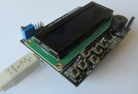
The LCD Keypad Shield is a popular expansion board that can be installed on the Arduino UNO board. It features a 2x16 character LCD screen, five push buttons (select, up, down, left, right) for navigation and selection, and a sixth button (Reset) to reset the Arduino board. To save digital pins, the buttons are connected to a single analog pin (AN0) via a voltage divider, which allows the analog value corresponding to each button pressed to be read. With CGB, the LCD screen requires the following pin numbers to be assigned: RS=portB.0, EN=portB.1, D4=portD.4, D5=portD.5, D6=portD.6, D7=portD.7, RW on Gnd A potentiometer on the shield allows you to adjust the display contrast (Backlight adjustement). The pins not used by the screen allow you to easily connect sensors or other components. In the demo files, select LCDCURSOR_4WIRE_TEST_mega328p.gcb
To avoid modifying the demo file, save it in a specific file (e.g., GCB_LCD.gcb). It is essential to modify the RS and Enable terminals for the Shiel LCD: Let's analyze a few lines of the program:
CLS clears the LCD screen Locate 0,0 indicates the location where line 0 (=top) position 0 will be written Print “Cursor ON” writes Cursor ON Locate 1,0 indicates the location where line 1 (=bottom) position 0 will be written LCDcursor CursorOn specific command indicating the display of a cursor ( _ ) wait 3 S wait 3 seconds
Click on Make Hex and Flash The LCD display activates... This gives an overview of the possibilities of the LCD library
Another tests For the remainder of my tests, I installed a connector to provide an I2C port. On the Arduino, the SDA line is on PC4 and the SCL line is on PC5. Note the pull-up resistors. I also installed a beeper on PC1. Using the Shield LCD Keypad and a Ds18B20 - Temperature measurement Installation of a terminal at the port Use of a DS18B20 temperature sensor In the demo files, select Temperature_Sensor_to_LCD_mega168.gcb
To avoid modifying the demo file, save it in a specific file (GCB_18B20)... You will need to change the circuit and specify #chip mega328p, 16. It is essential to modify the RS and Enable terminals. It is essential to specify the port to be used, A5, i.e., PC.5 with #define DQ PortC.5. Note the use of the ds18b20 library with #include <ds18b20.h>.
About the GCBasic libraries As with the Arduino IDE, which uses libraries to manage specific sensors or modules, GCBasic works with #include files. These files are already provided in the C:\GCstudio\gcbasic\include folder, so there is nothing to download. There are two types of libraries: - Internal (low-level) libraries: these correspond to standard PIC peripherals (USART, I²C, timers, text LCD, etc.). They are automatically integrated by the compiler when an associated command is used (PrintLCD..., I2CStart, etc.), so there is no need to include them manually. - Specific (high-level) libraries: these relate to specific sensors or modules (e.g. DS18B20, DHT11, ILI9341 displays, ST7735, etc.). In this case, you need to add an #include directive to your program.
If a library does not exist for your hardware, you can ask for help on the GCBasic forum, where the community often provides examples or new libraries.
Want to build a project?
Bring your design to life with the Elektor PCB Service, powered by Eurocircuits. Upload the project files and order professionally manufactured PCBs or assembled boards through a proven European production platform.
Supporting KiCad, Eagle, Gerber, and ODB++ formats, the service is suitable for everything from prototypes and validation builds to series production and volume manufacturing.
Elektor Magazine has been one of the leading sources of information on electronics for engineers, designers, start-ups and companies for 65 years. Our magazine is powered by an active community of electronics engineers – from students to professionals – who are passionate about designing and sharing innovative ideas.
For them, we publish hundreds of items a year, in formats such as articles, videos, webinars, and other learning formats. Our mission is to share knowledge in every possible way and inspire readers with the latest developments within the electrical engineering sector.
Thank you for your vote!
Leave further comments in the fields below.
Thank you for your vote!
If you wish to leave a comment with your rating, please first use the login below. If not, just close this window.


Discussion (1 comment)