
PSEUDO BALANCED MODULE
Ease for your XLR OUT TO XLR IN connections at a reduced price
The first time I heard of “pseudo balanced” was in the 90s when Soundcraft released their SPIRIT FOLIO mixer.
HF microphone receivers have often used this way of doing things.
This technique is also called impedance symmetry because there are 2 identical resistors at the output (R9, R11 & R10, R12), this in order to optimize the common mode rejection rate CMRR of the input assembly which will follow this module .
In fact, the output is indeed asymmetrical and not differential. We will rather talk about convenience wiring.
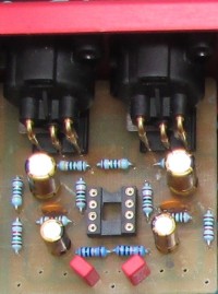
The PCB I made includes 2 Neutrik NC3MAH XLRs mounted on a plate, 1 AOP NE5532 and some components.
For the diagram, (C1, C2 & C7, C8) are connection capacitors.
R1, R2 set the input resistance. The gain is calculated like this:
GL = 1 + R5/R3 GR= 1 + R6/R4
If we want a gain of 10 dB to go from a 250 mV Cinch level to a 775 mV line level, R3, R4=10 K and R5, R6 =22K
In my configuration R13, C9 & R14, C10 constitute filters which are located on the power distribution bus V+, V-
This assembly has its place in short connection such as in Home studio, small sound system or to be integrated into vintage equipment.
For long connections, I recommend the THAT1646:
https://www.elektormagazine.fr/labs/balanced-audio-line-driver
HF microphone receivers have often used this way of doing things.
This technique is also called impedance symmetry because there are 2 identical resistors at the output (R9, R11 & R10, R12), this in order to optimize the common mode rejection rate CMRR of the input assembly which will follow this module .
In fact, the output is indeed asymmetrical and not differential. We will rather talk about convenience wiring.
The PCB I made includes 2 Neutrik NC3MAH XLRs mounted on a plate, 1 AOP NE5532 and some components.
For the diagram, (C1, C2 & C7, C8) are connection capacitors.
R1, R2 set the input resistance. The gain is calculated like this:
GL = 1 + R5/R3 GR= 1 + R6/R4
If we want a gain of 10 dB to go from a 250 mV Cinch level to a 775 mV line level, R3, R4=10 K and R5, R6 =22K
In my configuration R13, C9 & R14, C10 constitute filters which are located on the power distribution bus V+, V-
This assembly has its place in short connection such as in Home studio, small sound system or to be integrated into vintage equipment.
For long connections, I recommend the THAT1646:
https://www.elektormagazine.fr/labs/balanced-audio-line-driver
Want to build a project?
Bring your design to life with the Elektor PCB Service, powered by Eurocircuits. Upload the project files and order professionally manufactured PCBs or assembled boards through a proven European production platform.
Supporting KiCad, Eagle, Gerber, and ODB++ formats, the service is suitable for everything from prototypes and validation builds to series production and volume manufacturing.
Made in Europe. Fast. Reliable. Professional.
Updates from the author