


Stereo Opto-Limiter
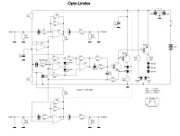
I needed a basic Limiter for podcasting purposes after a fairly cheap commercial unit had failed. Rather than buy another, I decided to try to develop my own.

I found that I had a bag of LCR0202 "Vactrols". These are little black plastic boxes which contain a Light Dependant Resistor illuminated by an LED. I decided to try these, and went through the ones I had in stock to find the best matching pair. I tested very simply by connecting the LED side through a 1kΩ resistor to a 6V supply, and measuring the resistance across the LDR terminals. I found that when powered like this, I'd get a resistance of about 6 - 10 kΩ.
I sorted the ones I had in stock into pairs, and found that - out of a bag of 23 pieces - I got nine accurately matched pairs!
The next step was to develop the audio part of the circuit. I wanted roughly unity gain through the circuit until the Limit point was exceeded, at which point I wanted the output level to remain substantially constant.
Level detection was achieved very easily, by combining the outputs of the op-amp audio stages at high impedance to mono (so as not to introduce significant crosstalk), and using a fairly standard rectifier configuration to provide a DC voltage proportional to the instantaneous audio level. This DC signal is then fed to a time constant circuit that has a low resistance path to charge the timing capacitor, and a higher value to discharge it. This gives a fast attack, and a slowed decay - which is just the kind of characteristic I prefer in my Limiters. I then used a simple transistor buffer to provide enough current to drive the LEDs in the LCR0202s. I added a "Limiting" red LED for the front panel, and a green LED to indicate the presence of power.
Initial testing of a Veroboard prototype was successful, though I changed a couple of component values to get the performance as I wanted it.
The first prototype used a bipolar supply (+/- 9V) so that I had the option of battery power, but quickly realised that the current drain would be assymetrical, leading to one battery discharging faster than the other! I realised that with the addition of a further op-amp, I could easily derive a low-impedance "half-rail" and run the whole thing from a single supply. That is the circuit shown here.
I used an NE5532 for the stereo audio paths, a TL071 for the half-rail supply, and a TL072 for the rectifier stages.
In use, the operation of the device isn't noticeable, unless the levels are quite a long way "over", when "pumping" becomes obvious. The NE5532 lives up to its reputation as a low noise, low distortion dual op-amp, and the other parts really aren't critical. I found (on testing with an audio analyser) that the Vactrols do introduce a little distortion, but the amount isn't enough to be objectionable, and the circuit prevents the web audio server from disconnecting because of over-level. With the addition of "guard clippers" this could be used for broadcasting, but I'd prefer something a bit more sophisticated for that purpose.
The only significant disadvantage of this circuit is the need to select a stereo matching pair of Vactrols. The LCR0202 seems to have a fairly wide production spread, but I'd expect to find a few pairs if I bought a bag of ten pieces. There are more expensive Vactrols available from many suppliers, made by Clairex or Silonex, and I'd expect these to be better matched (they cost a lot more), but I'm happy enough with my cheap, quick Limiter.
Want to build a project?
Bring your design to life with the Elektor PCB Service, powered by Eurocircuits. Upload the project files and order professionally manufactured PCBs or assembled boards through a proven European production platform.
Supporting KiCad, Eagle, Gerber, and ODB++ formats, the service is suitable for everything from prototypes and validation builds to series production and volume manufacturing.
Made in Europe. Fast. Reliable. Professional.
Updates from the author