


TRRS CHECKING
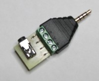
We often encounter problems around a TRRS connection given the 2 standards
The thought I often hear: my headphones work but my microphone does not. The following tells you more.
The TRRS connection is often talked about with 2 cabling possibilities for the MEMS micro given the Android or Apple configuration.
I will provide you with explanations with the use of a TRRS Delock 65453 adapter which allows you to have the 4 free points to be able to take multimeter measurements.
If between (S) Shield and R (Ring), you measure a positive voltage of 1 to 2.5V, you are in a OMTP configuration (GND, MIC, Right, Left). If on the other hand you have a voltage of -1 to -2.5V, this is a CTIA configuration (MIC, GND, Right, Left)
You can check each connection to the TRRS Micro headset label (Smartphone, Iphone, Tablet, PC, Games, ...)
The little PCB that follows my adapter is nothing more than a micro crossover.
The trend is the configuration (MIC, GND, Right, Left). In the case of DIY, it is imperative to use isolated connectors because the Micro connection would be put to the chassis
It can also be inserted into a camcorder, camera, HF microphone pack, in order to locate connections (Alim electret)
Je vous invite également à revoir mon article sur le Smart DI Box : https://www.elektormagazine.fr/labs/smartphone-di-box
I also invite you to review my article on the Smart DI Box: https://www.elektormagazine.fr/labs/smartphone-di-box
Over time, my tests indicate that the CTIA standard is widely adopted for both Android and PC laptops. Only an old Nokia was in OMTP. So for DIY let's adopt the CTIA wiring.
The TRRS connection is often talked about with 2 cabling possibilities for the MEMS micro given the Android or Apple configuration.
I will provide you with explanations with the use of a TRRS Delock 65453 adapter which allows you to have the 4 free points to be able to take multimeter measurements.
If between (S) Shield and R (Ring), you measure a positive voltage of 1 to 2.5V, you are in a OMTP configuration (GND, MIC, Right, Left). If on the other hand you have a voltage of -1 to -2.5V, this is a CTIA configuration (MIC, GND, Right, Left)
You can check each connection to the TRRS Micro headset label (Smartphone, Iphone, Tablet, PC, Games, ...)
The little PCB that follows my adapter is nothing more than a micro crossover.
The trend is the configuration (MIC, GND, Right, Left). In the case of DIY, it is imperative to use isolated connectors because the Micro connection would be put to the chassis
It can also be inserted into a camcorder, camera, HF microphone pack, in order to locate connections (Alim electret)
Je vous invite également à revoir mon article sur le Smart DI Box : https://www.elektormagazine.fr/labs/smartphone-di-box
I also invite you to review my article on the Smart DI Box: https://www.elektormagazine.fr/labs/smartphone-di-box
Over time, my tests indicate that the CTIA standard is widely adopted for both Android and PC laptops. Only an old Nokia was in OMTP. So for DIY let's adopt the CTIA wiring.
Want to build a project?
Bring your design to life with the Elektor PCB Service, powered by Eurocircuits. Upload the project files and order professionally manufactured PCBs or assembled boards through a proven European production platform.
Supporting KiCad, Eagle, Gerber, and ODB++ formats, the service is suitable for everything from prototypes and validation builds to series production and volume manufacturing.
Made in Europe. Fast. Reliable. Professional.
Discussion (0 comments)