


Article
simple 555 tester
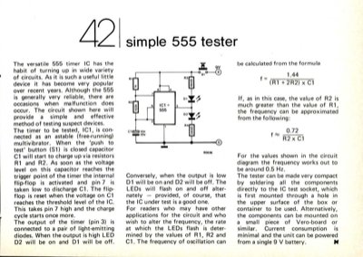
The versatile 555 timer IC has the habit of turning up in wide variety of circuits. As it is such a useful little device it has become very popular over recent years. Although the 555 is generally very reliable, there are occasions when malfunction does occur. The circuit shown here will provide a simple and effective method of testing suspect devices. The timer to be tested, IC1, is con- nected as an astable (free-running) multivibrator. When the "push to test" button (S1) is closed capacitor C1 will start to charge up via resistors R1 and R2. As soon as the voltage level on this capacitor reaches the trigger point of the timer the internal flip-flop is activated and pin 7 is taken low to discharge C1. The flip- flop is reset when the voltage on C1 reaches the threshold level of the IC. This takes pin 7 high and the charge cycle starts once more. The output of the timer (pin 3) is connected to a pair of light-emitting diodes. When the output is high LED D2 will be on and D1 will ...
Want to build a project?
Bring your design to life with the Elektor PCB Service, powered by Eurocircuits. Upload the project files and order professionally manufactured PCBs or assembled boards through a proven European production platform.
Supporting KiCad, Eagle, Gerber, and ODB++ formats, the service is suitable for everything from prototypes and validation builds to series production and volume manufacturing.
Made in Europe. Fast. Reliable. Professional.
Discussion (1 comment)