


DIY Lithium Battery Health Monitor
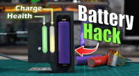
What You'll Build: A compact device that displays State of Charge (SoC) and State of Health (SoH) of lithium batteries using LED bars. Perfect for salvaging old cells or DIY power banks! Key Features: - Real-time monitoring via BQ27441 fuel gauge IC - Dual LED bars for SoC/SoH (WS2812B NeoPixels) - USB-C charging (BQ24075 IC) - Open-source design (PCB/code/3D files included)
Supplies
- BQ27441 Fuel Gauge IC (Texas Instruments)
- BQ24075 Charger IC (Texas Instruments)
- ATmega328P MCU (Arduino-compatible)
- WS2812B LED Bars (10x2 configuration)
- 18650 Battery Holder
- 0.01Ω Current-Sense Resistor (1206 package)
- USB-C Connector (TYPEC-304-BCP16)
- Custom PCB → Order from JLCPCB
- Solder Paste (ChipQuik SMD291AX)
- MHP50 Hot Plate
- Flux Remover (Chemtronics Flux-Off)
- Soldering Station (Hakko FX888D)
- LINKMICRO Digital Microscope
- ESD-Safe Tweezers (5-piece set)
- ANENG AN8008 Multimeter
- PLA Filament (Overture Black)
- M2 Threaded Inserts
- Altium Designer → Full Project design files (Altium 365)
- Arduino IDE
Schematic Overview
- BQ27441 Fuel Gauge - For accurate SoC/SoH measurement via I²C
- BQ24075 Charger - Handles USB-C power input and battery charging
- ATmega328P MCU - Processes data and drives LED indicators

- Precision Sensing: Added a 0.01Ω current-sense resistor (R10) for coulomb counting
- Thermal Safety: Designed dual NTC support (onboard and external battery sensors)
- Noise Reduction: Used star grounding and 100nF decoupling caps near all ICs
Design Tools Used
- Schematic Capture: Altium Designer
- Component Sourcing: Selected JLCPCB-compatible parts for easy assembly
Pro Tip:
- Solder Paste (ChipQuik SMD291AX)
- MHP50 Hot Plate
- LINKMICRO Microscope
- PCB Stencil (Included in GitHub repo’s Gerber files)
Assembly Process
- Secure the PCB stencil over the board using tape.
- Spread solder paste evenly with a squeegee (or old credit card).
- Pro Tip: Chill the paste for 5 mins first for better viscosity!
- I 3D printed a support to help me apply solder paste → (3D STL File here)

- Use ESD tweezers to position tiny parts (0402 resistors, ICs).
- Start with the smallest components (resistors/caps) → larger ICs last.

- Preheat the MHP50 hot plate to 150°C.
- Place the PCB on the plate and heat until paste turns shiny (~220°C, 2-3 mins).
- Critical: Let it cool naturally, no fans!

- Check each joint with the LINKMICRO microscope:
- Good joint: Smooth, concave fillet.
- Bad joint: Dull or ball-shaped (reflow with hot air).
- Pay special attention to:
- BQ27441’s tiny pins (SON-12 package)
- USB-C connector (easy to bridge)
Troubleshooting
- Bridged Pads? Use copper braid w/ flux to wick excess solder.
- Tombstoning? Redo paste application, uneven amounts cause this.
- Cold Joints? Reheat with hot air gun at 250°C.

Pro Tips
- Stencil Alignment: Use PCB fiducials for perfect paste deposits.
- Double-Sided Boards: Assemble bottom side first (larger components last).
- No Hot Plate? A skillet works in a pinch (monitor with IR thermometer).

- 3D-Printed Parts (STL Files)
- M2 Threaded Inserts and screws
- Assembled PCB (from Step 2)
- Soldering Iron (for insert installation)

- Heat the inserts with a soldering iron at 200°C and press into housing holes.
- Pro Tip: Use an M2 screw to align inserts vertically while cooling.

- Secure the board with M2 screws, ensuring USB-C port aligns with the housing cutout.
- Connect the 18650 holder/JST connector.

- Snap the 3D-printed light guides over the WS2812B LEDs for even glow.

- Tools Needed:
- USBASP Programmer (for bootloader)
- Arduino IDE (for firmware)
Flashing Process
- Upload Bootloader (ISP Port)
- Connect USBASP to the PCB’s 6-pin ISP header.
- Select ATmega328P and burn Arduino Nano Bootloader.

- Upload Firmware
- Open Battery_health.ino in Arduino IDE.
- Set board to "Arduino Nano" (same chip).
- Adjust BATTERY_CAPACITY in code to match your cell (e.g., 3000 for 3000mAh).
- You can get the code from here → GitHub direct link
Testing with Used Batteries
- Insert Cells (try 3 scenarios):
- Healthy cell: SoH ≈100%, SoC updates smoothly.
- Aged cell (e.g., laptop pull): SoH <80%, LED bar shows degradation.
- Dead cell: SoH <20%, verify charger blocks over-discharge.

- Validate Accuracy
- Compare SoC readings to a bench power supply at known voltages.

- Compare SoC readings to a bench power supply at known voltages.
- Bootloader Issues? Double-check ISP pin connections with a continuity tester.
- No USBASP? Use an Arduino-as-ISP (tutorial in here).
- Calibration: For lab-grade accuracy, log data in BQStudio (Texas Instruments’ tool).
Want to build a project?
Bring your design to life with the Elektor PCB Service, powered by Eurocircuits. Upload the project files and order professionally manufactured PCBs or assembled boards through a proven European production platform.
Supporting KiCad, Eagle, Gerber, and ODB++ formats, the service is suitable for everything from prototypes and validation builds to series production and volume manufacturing.
Made in Europe. Fast. Reliable. Professional.
Discussion (3 comments)