For activities such as tinkering with amplifiers, sensors, and microcontrollers like Arduinos, ESPs, Raspberry Pis, or repairing consumer electronics, a 100 MHz bandwidth and two channels are entirely sufficient. A frequency or function generator for generating test signals or checking filters also is practical in many applications. With the FNIRSI 1014D, you get both functions in one device.
Besides a soldering station, a multimeter, and a power supply, the next essential tool to consider in an electronics workshop is an oscilloscope. However, for a hobbyist workshop, there is no need for a device with a 500 MHz bandwidth, numerous channels, or sophisticated analysis functions. For activities such as tinkering with amplifiers, sensors, and microcontrollers like Arduinos, ESPs, Raspberry Pis, or repairing consumer electronics, a 100 MHz bandwidth and two channels are entirely sufficient. A frequency or function generator for generating test signals or checking filters also comes in handy in many applications. With the FNIRSI 1014D, you get both functions in one device.
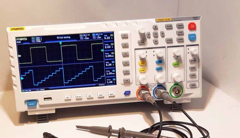
The scope comes with two switchable probes (1× and 10×), a USB power supply, a manual, and a probe adjustment tool. The oscilloscope is powered by a USB power supply that provides 2 A at 5 V. With dimensions of 310 mm × 145 mm × 70 mm, it is compact and portable, yet large enough to be operated comfortably. With fold-out stands, it sits at a good angle on the lab bench.
Frequency Generator with 14 waveforms up to 10 MHz (sine)
USB Export
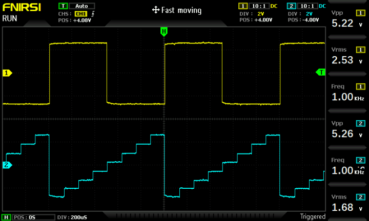
As is customary with digital oscilloscopes, in addition to signal representation, values such as voltage (peak, RMS, minimum, maximum, etc.), frequency, and duty cycle are displayed numerically. Users can select which values to display from a menu. Two cursors allow precise measurement of time intervals and voltages. An auto-set function automatically configures the oscilloscope to sensible signals based on the current input signal. Even a simple FFT representation of the signal can be displayed. Waveforms and Measurement Results.
The FNIRSI-1014D can handle a maximum input voltage of 400 volts. Triggering can be set on the rising or falling edge. The scope also features an automatic triggering function that works reliably.
Power Supply: USB PSU or Power Bank
In addition to the standard USB power supply, the scope can also be operated by a power bank. In this case, the oscilloscope is completely electrically isolated, allowing measurements in switching power supplies, etc., without the need for an isolation transformer. This alone makes the FNIRSI 1014D worthwhile for this application, saving the expense of costly differential probes, which, even in a budget version, cost as much as the oscilloscope. Additionally, by using a power bank, the scope becomes very portable and can be used in any location, such as power racks or cars.
Using a standard 12 Ah (I max > 2 A) power bank, the FNIRSI 1014D runs for about 5 hours in continuous operation. This will be sufficient for most applications.
Warning: The FNIRSI 1014D manual states that “the original power supply must be used.” So using a power bank is at your own risk, even though no problems came up during the tests.
Subscribe
Tag alert: Subscribe to the tag Test & Measurement and you will receive an e-mail as soon as a new item about it is published on our website!
Performance Check
Regarding the specified bandwidth of 100 MHz, some things should not be overlooked. To measure a signal with a maximum frequency component of 50 MHz, an oscilloscope with a bandwidth of 100 MHz is required. If a measurement should be truly meaningful and well-resolved, the commonly used guideline is the 1:5 rule. An oscilloscope with a 100 MHz bandwidth can effectively and accurately display a signal with a maximum frequency component of 20 MHz.
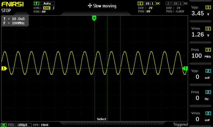
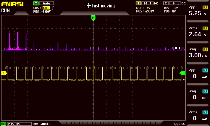
For measurements on Arduinos, audio amplifiers, Raspberry Pi, etc., a 100 MHz bandwidth is completely sufficient. Nevertheless, the specified bandwidth of the FNIRSI 1014D of 100 MHz is somewhat on the high side. The device barely meets the classical −3 dB bandwidth criterion, even though it displays a 100 MHz signal in an acceptable way. A 100 MHz, 5 V signal on the FNISRSI-1014D
For further details, see the section “For professionals: Bandwidth and sampling rate.” below.
The minimum sensitivity of 50 mV/div is not spectacular. Typically, a sensitivity of at least 10 mV/div is available on most DSOs. Nevertheless, the measured values are within the specified tolerances, and the analysis options are satisfactory.
Saving and Analyzing Signals
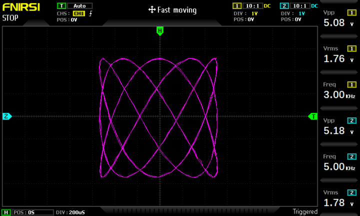
All measurements can be saved as a screenshot and/or waveform and accessed through a gallery view. When saving a waveform, it can be analyzed even after the measurement, as if the measurement signals were still present. For waveforms and screenshots, 1 GB of internal memory is available, which can be read out via a computer. During USB operation, the FNIRSI 1014D is simply recognized as a removable disk, and no drivers or additional software are required. X/Y Operation and Lissajous Figure
No advanced functions, such as mathematical functions, bus decoding, etc., are available, which is acceptable given the price point. Nevertheless, a simple Fourier Transform display is provided. As it does not allow detailed measurement applications, its value is limited to simple harmonic analysis. The FFT display is quite simple
For Professionals: Bandwidth and Sampling Rate
As mentioned earlier, the specifications regarding bandwidth (100 MHz) and sampling rate (1 GSa/s) are a bit ‘stretched’. The terms ‘sampling rate’, ‘bandwidth’, and ‘oversampling’ are crucial in the context of oscilloscopes as they influence the performance and accuracy of these devices.
Here are some basics: The sampling rate refers to the number of data points an oscilloscope records per second and is measured in Samples/s (1 GS/s = 1,000,000,000 Samples per second). A higher sampling rate allows for a more accurate reconstruction of fast signals. The sampling rate must be sufficiently high to appropriately represent a waveform. According to the Nyquist-Shannon sampling theorem, the sampling rate should be at least twice the highest frequency component of the signal to be analyzed to ensure correct reproduction. Therefore, for a signal with a maximum frequency of 100 MHz, a sampling rate of at least 200 MS/s (200 Mega Samples per second) is required.
Oversampling involves the oscilloscope operating with a sampling rate significantly higher than the minimum sampling rate required for displaying the signal. It allows oscilloscopes to capture signals with higher accuracy, especially when it comes to displaying rapid signal changes.
An oscilloscope can capture the signal with a high sampling rate and then use digital signal processing techniques to generate a more accurate representation of the signal. This enables better capture of details and rapid signal events. In summary, the sampling rate indicates how many data points per second an oscilloscope records, while oversampling is a technique where the oscilloscope operates with a higher sampling rate to capture and display more accurate signal information.
Therefore, a sampling rate of 1 GigaSample/s (= 1000 MegaSample/s) is well-suited for a 100 MHz bandwidth (5× oversampling). Unfortunately, the FNIRSI 1014D has a real-time sampling rate of only 200 MSamples/s, not 1 GSample/s. It employs two 2-channel analog-to-digital converters with 100 MHz in interleaved mode. The scope employs a medium-performance ADC and uses successive shifted sampling, requiring a stable signal to combine the actual waveform.
A real-time oscilloscope, as the name suggests, digitizes the input in real time by sampling fast enough to accurately capture and display an incoming signal. Each data point on the display has been sampled directly after the previous point. These instruments are sometimes called single-shot scopes based on their ability to capture a signal with a single acquisition. A sampling oscilloscope, on the other hand, uses a ‘sweep’ across a time window. This is done by adding a small, fixed delay with each iteration. This works only with repetitive signals. Using this technique, an ‘effective’ sampling rate of 1 GS/s is achieved by the FNIRSI 1014D.
Another issue is averaging. Usually, the averaging depth can be adjusted. The FNIRSI 1014D obviously uses fixed averaging. This usually indicates that there is something to hide. In this case, the FNIRSI 1014D implements some mathematical tricks to compensate for the limited bandwidth and sampling rate or the low sensitivity.
Finally, the bandwidth of an oscilloscope refers to the frequency at which the amplitude of the oscilloscope's input signal is attenuated by 3 decibels (dB) compared to its low-frequency value. In other words, it is the frequency at which the voltage amplitude of a sinusoidal input signal is reduced to approximately 71% of its original value. For oscilloscopes, the −3 dB bandwidth is a critical parameter because it indicates the range of frequencies that the oscilloscope can accurately capture and display. In practical terms, a signal with a frequency equal to the −3dB bandwidth is still displayed on the oscilloscope, but its amplitude is reduced by approx. 30% compared to lower frequencies. Beyond the −3 dB point, the oscilloscope's ability to faithfully represent higher-frequency components of a signal diminishes. This usually implies that the pass band is flat. This is the main issue of the FNIRSI 1014D. The frequency response is not smooth and barely meets the 100 MHz mark.
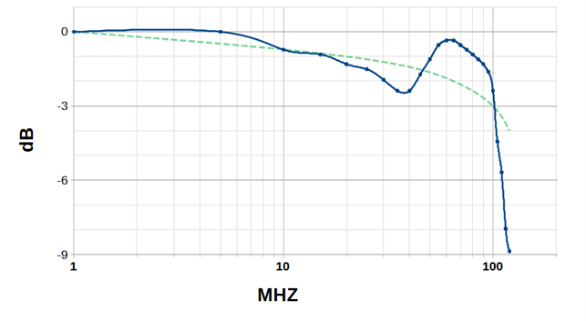
Measured Bandwidth of the FNIRSI-1014D
The green line indicates the usual roll-off of an oscilloscope. The blue data line was measured on the FNIRSI 1014D device. So, even if the −3 dB criterion for a 100 MHz signal is met, the wobbly pass band may lead to incorrect measurement results at higher frequencies.
The Function Generator
One of the most intriguing features of the FNIRSI 1014D is its integrated function generator. Although it may not be as crucial as an oscilloscope itself, a generator is a standard tool in most electronics labs. Whether for testing amplifiers, resonators, or serving as a reference clock for digital circuits, a function generator is indispensable.
The FNIRSI 1014D generator offers the following features:
Fixed peak-to-peak amplitude of 2.5 V
Frequency range: 1 Hz to 10 MHz (sine); 1 Hz to 2 MHz (all others)
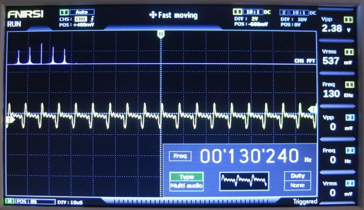
Unfortunately, the amplitude of the generator is fixed at 2.5 Vpp, limiting its versatility to a certain extent. Nevertheless, most standard applications, such as checking resonance curves or audio amplifiers, remain possible. Thanks to the variable duty cycle, pulses and asymmetric square waves are also available. Integrated Function Generator
So, the integrated frequency generator can replace an additional device on the workbench, as long as no special features are required.
Pros and Cons
All in all, the test results lead to the following impression:
Pros
Easy to use
Small size but big screen for the size
Sharp and bright display with all information (Vpp, Vavg, frequency, etc.) clearly visible
Function generator with BNC connector on the front is included
Basic FFT function is available
Powered by USB (5 V, 2 A), battery powering easily possible
Cons
No math functions (add, subtract, etc.)
Fixed averaging
‘Unusual’ pass band shape
1 GigaSample/s only in sampling mode
Conclusion
The FNIRSI 1014D will probably not find its way into many high-end research and development laboratories. However, for those looking for an affordable entry-level device, it serves its purpose well. Its strengths do not lie in high-frequency measurements or extreme precision of signal magnitudes. Nevertheless, for most tasks involving Arduino, ESP32, or the Raspberry Pi, the device can undoubtedly provide useful services.
All in all, the FNIRSI 1014D is an affordable, portable digital oscilloscope with two channels and sufficient features and performance. It is well-suited for hobby workshops, schools, electronics enthusiasts, or common repair tasks.
Elektor Magazine has been one of the leading sources of information on electronics for engineers, designers, start-ups and companies for 65 years. Our magazine is powered by an active community of electronics engineers – from students to professionals – who are passionate about designing and sharing innovative ideas.
For them, we publish hundreds of items a year, in formats such as articles, videos, webinars, and other learning formats. Our mission is to share knowledge in every possible way and inspire readers with the latest developments within the electrical engineering sector.
Thank you for your vote!
Leave further comments in the fields below.
Thank you for your vote!
If you wish to leave a comment with your rating, please first use the login below. If not, just close this window.

Discussion (5 comments)