
DIY LiPo Supercharger Kit: A GreatScott! and Elektor Collaboration
on
For experimenting with electronics, we are used to our trusty power supplies on a lab bench. While this is the usual way to get prototypes up and running the leads sometimes become a bit of a handicap if the device we build is meant to be portable or moving around the lab. The workaround can be a bunch of batteries carefully crafted with duct tape, hot glue and some cheap DC/DC converter into a kind of portable battery pack. That works for a prototype, but it isn’t that nice, especially if you need 5 or 12 V for your device. This can be done in a better way and it has. After meeting at the 2019 productronica fair in Munich, Elektor and popular engineer GreatScott! decided to team up to develop a handy DIY kit just for you. The result is the new DIY LiPo Supercharger Kit!
The GreatScott-Elektor collaboration
Who is GreatScott? Great Scott! is the name of a Youtube channel launched back in 2013 presenting electronic projects and knowledge to more than 1 million subscribers. The videos include a wide variety of DIY projects that viewers can recreate. Many other videos offer inspiration and clear solutions to engineering problems. As a few videos have already launched featuring Elektor products, the idea came up to present a DIY kit that everyone that is interested can use to expend their knowledge and skills.
GreatScott! has sketched the raw schematic of a LiPo powered, rechargeable supply that shall be user buildable with SMD components. All the components and ingredients look not that complicated on first sight, a charging IC for LiPo batteries, a DC/DC converter to provide 5 V and 12 V and a battery protection IC. All components are chosen to be 1206 in size where possible, to allow even beginners to get all SMD components onto the PCB and hopefully show that soldering SMD is not a kind of black magic that only well trained wizards can do. Parts that need some kind of special attention are already built onto the PCB to make your start into SMD assembly even a bit easier and avoid dealing with small pins and pads underneath ICs.
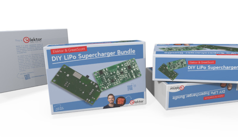
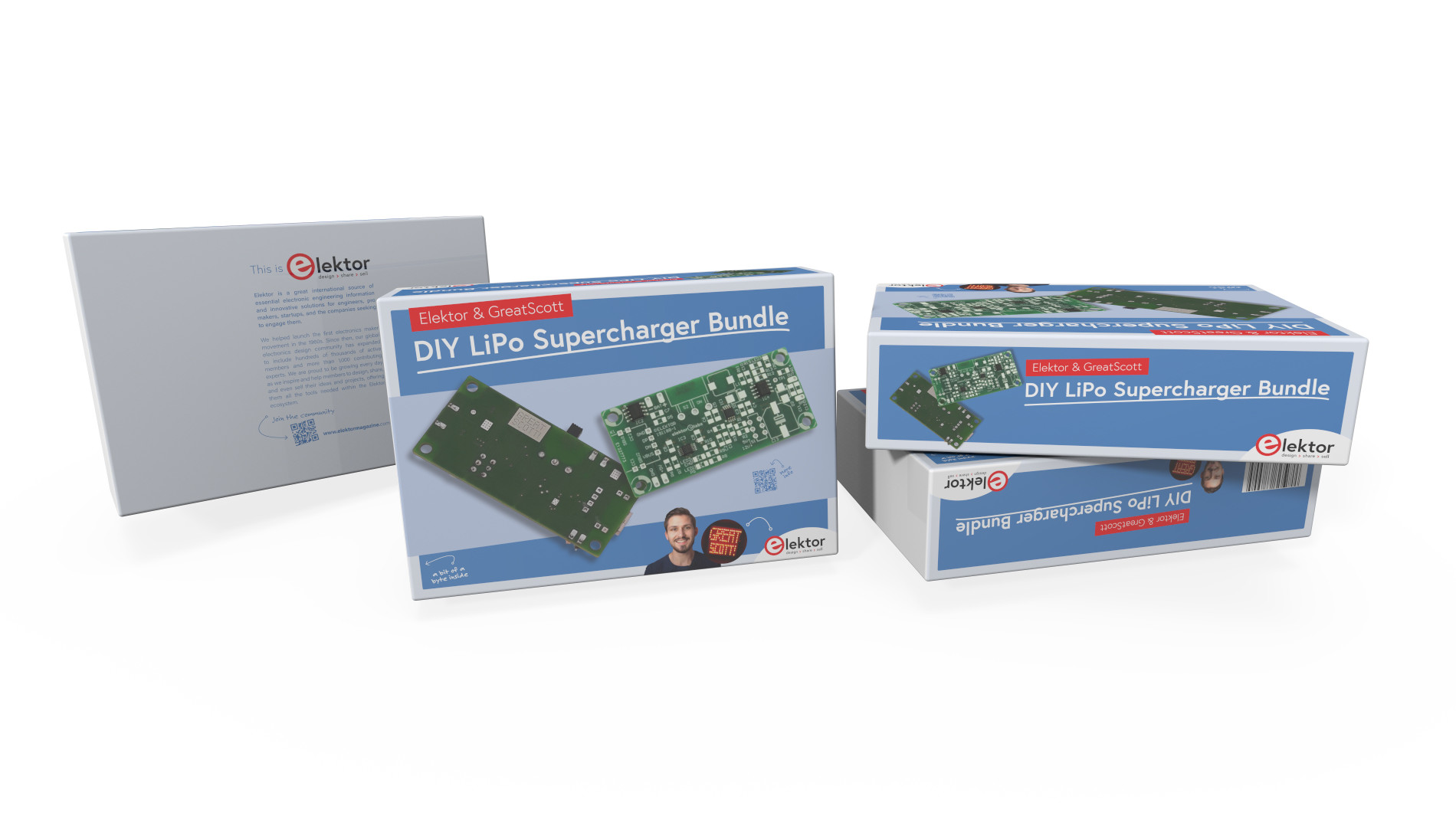
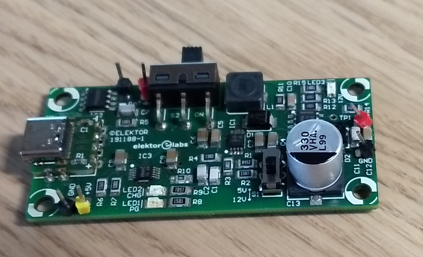
For charging you can use direct attached cables providing 5 V or use the USB-C connector on the add-on PCB to provide power to recharge the battery. With USB-C it is a lot easier to connect the plug in the right orientation and the connector on the PCB itself is held in place by four THT mounting holes for more stability. Besides using the power supply a fun part of the project is building it in the first place. And this comes with a nice step-by-step guide included in the package. Refer to Figure 1 a first look.
The three ICs that make the board work are from a well-known vendor. The battery protection IC is a XB8089D from Xysemi, a chip only found at distributors that specialize in Chinese silicon products. This chip handles overcharge, over discharge, over current and reverse polarity protection in a small SOP8 package with expose pad for a reasonable price. While many batteries used in products like drones have integrated protection, it won’t be safe to remove this chip from the circuit if a lithium battery without protection is installed.
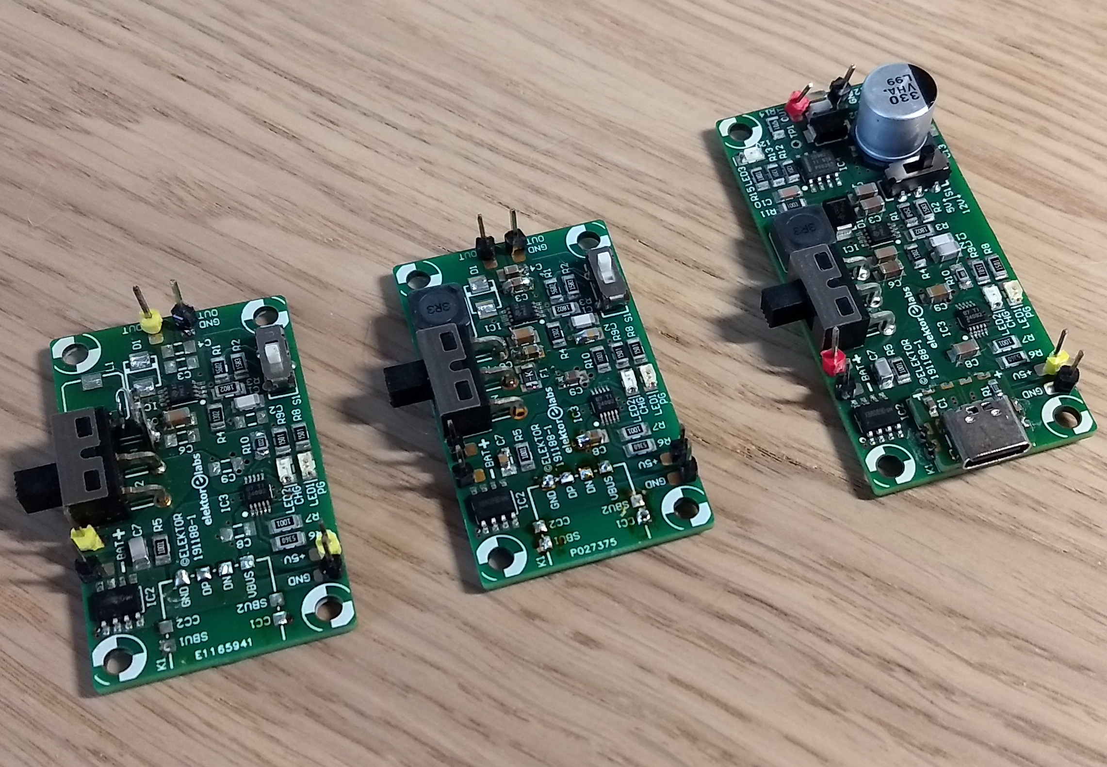
With the sketches and rough schematic GreatScott provided, Elektor added their experience in creating and designing PCBs. You might think this is the end of the story (you have a PCB and everything is fine), but as rule of thumb, it usually takes three iterations, as you can see at Figure 2.
How the DIY LiPo Supercharger works
The first DIY LiPo Supercharger prototype worked almost as expected besides a few minor issues, like not charging the battery or disintegrating the DC/DC converter if load exceeded a certain point. The battery protection IC will prevent the lithium battery form becoming damaged ( sort of ) but the current limit is at 10 A (meaning 37 W), so the DC/DC converter disintegrated at around 15W. And the charging, that was an easy fix, as there was somewhere a typo, making the desired 10 k resistor a 100 k resistor, it was just a short swap of components. But to be honest, we know where to look when it comes to the wrong resistor for charging as we have seen this in other projects before. The chosen BQ24092 comes from a BQ2409x line and this is where you need to check the datasheet carefully. Depending on the chip the mentioned resistor needs to be 10 k or 100 k, and it was easier to change the resistor than the whole charger IC.
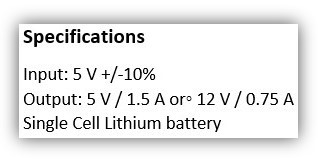
There are more lessons learned as we did three iterations. How to fix the disintegrating DC/DC converter is something that is quite simple if you know what parts you can choose. Also some do's and don'ts were made during the iterations, and for manufacturing we may have also a few lessons learned you can benefit from. Meanwhile you can check out the Youtube channel of GreatScott! and see the assembly and the power supply in action. Details and an in-depth description of the circuitry will follow next time. The rough specifications are presented in the nearby textbox.
The final revision of the PCB looks like what you see in Figure 3.
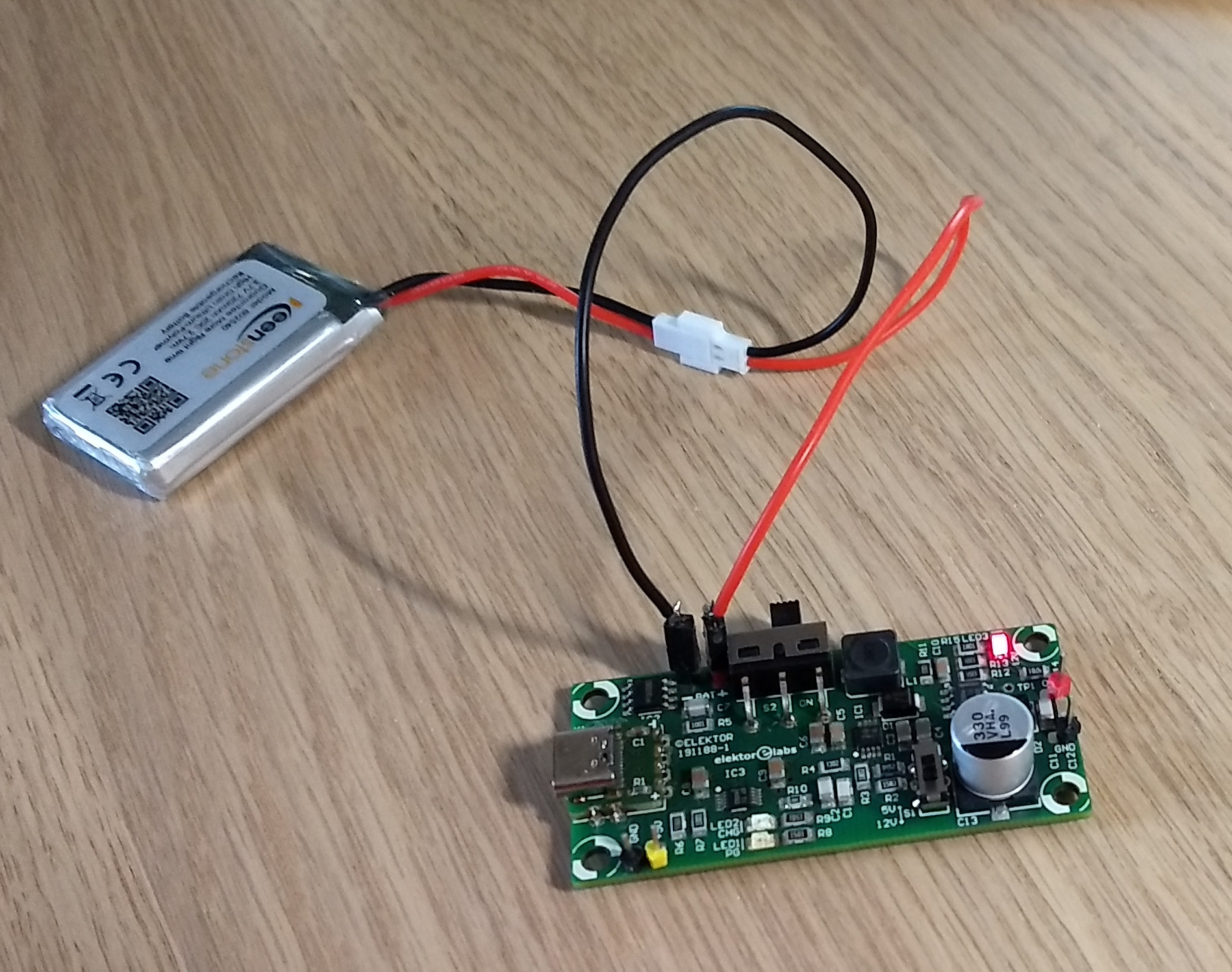
Take a look at the DIY LiPo Supercharger in action (Figure 4).
Discussion (0 comments)