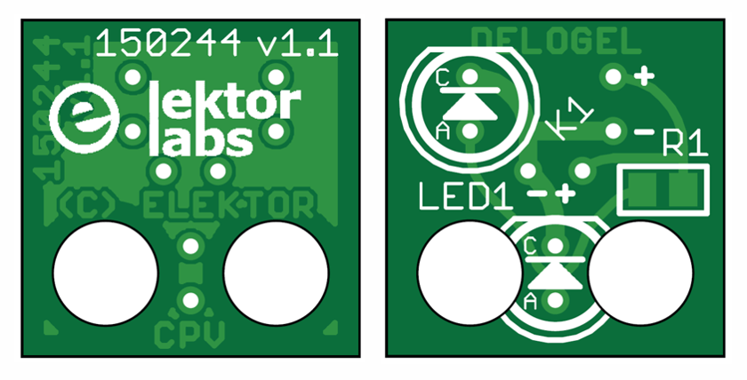
After some experiments we found that to be versatile a Lego-compatible LED must have options. Some people want to put the LED inside a construction (like a light inside a house), others want it on the outside (like a street light). Our PCB shown in Figure 2 can do both, thanks to two LED footprints. Big LEDs or small, you can even fit SMD types if you like. Respect the polarity though, otherwise the ‘+’ and ‘–‘ symbols on the PCB will be wrong. Do not fit two LEDs on the board.
Figure 2. The carefully designed PCB for the Lego LED. Note the two LED footprints and the
different positions available for the LED connector. Select the one that fits your application best.
It’s up to you how to connect or wire the LED module to a supply or a controller system. We’ve a preference for a 90-degree 2-way pinheader socket, but in which direction? To get out of this pickle we put two connector footprints ‘K1’ on the PCB, allowing you to position a connector any way you like it: top mount or bottom, horizontal or vertical, North, South, East, West — whatever you like.



Discussion (0 comments)