
LED Booster for Microcontrollers
on
There’s many a time when you want to connect a white LED to a microcontroller operating from a 3 V supply voltage. Unfortunately, this doesn’t work and your nice white LED only lights up feebly or not at all.
Why does it work perfectly with red and green LEDs, but not with white? A bit of data sheet research reveals the reason: white LEDs have a forward voltage of 3.2 V, so a 3 V supply is simply not enough to let them light up properly. The advice you often see in online forums is to use a boost converter to generate a higher voltage, along with a transistor switch to control the LED. For just a single LED, this seems like a lot of overhead.
The good news is that there’s an easier way. And it only needs one inexpensive component: an inductor, which costs next to nothing. If you wire it up right and drive it the right way, your white LED will light up nicely — and this even works with a microcontroller supply voltage as low as 2.5 V. Magic? Not at all.
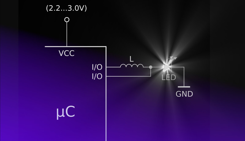
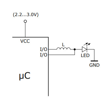
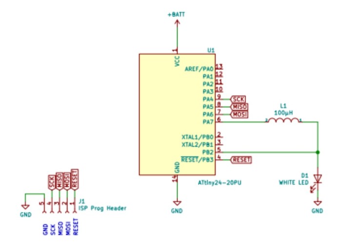
The circuit shown in Figure 1 is a boost converter. It also goes by other names, such as step-up converter. But how does this minimalistic boost converter work?
Operating principle of a boost converter
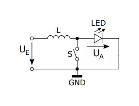
Take an inductor L (a coil) and connect one end to the input voltage UIN and the other end to a switch S tied to ground. When the switch S is closed, a gradually rising current flows through the inductor L, creating a magnetic field. When the switch S is opened a bit later the magnetic field collapses, generating an inductive voltage over the coil (Figure 2), the same as an ignition coil in a car.

This voltage adds to the supply voltage, so the voltage UOUT (UA in the drawing) )at the diode D (which charges the capacitor C) is higher than the supply voltage. When the switch S is closed again, this process repeats. A LED is basically just a diode, so the diode D can be replaced by a LED (Figure 3). And the LED can be connected directly to ground.
Now you’re probably wondering how this LED boost converter can be implemented using a microcontroller with only one additional component, in the form of an inductor. For this we take advantage of the different I/O pin modes. A microcontroller I/O pin can be set to push-pull mode or to open-drain mode. Push-pull means that the pin is switched to VCC for a logic 1 (high) or switched to GND for a logic 0 (low), as shown in Figure 4. With the open-drain setting, by contrast, the output is open for a logic 1 and switched to GND for a logic 0. That’s exactly the same as the switch S in the circuit described above.

The value of the inductor depends on the switching frequency, the current, the input voltage and the output voltage. The following approximate formula for determining the inductor value can be found in most data sheets for boost switching regulators:
L = UIN × (UOUT – UIN) / (∆IL fs × UOUT)
where L = inductance [H], UOUT = output voltage [V], UIN = input voltage [V], IOUT = output current [A], fs = switching frequency [Hz], ∆IL = inductor ripple current [A]
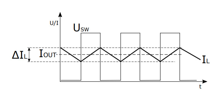
The inductor ripple current ∆IL is the difference between the minimum and maximum current through the coil. In other words, it is the peak-to-peak waveform of the average (DC) current through the coil (Figure 5).
The current through the coil always differs from the output current by a few percent. This is why most data sheets from boost switching regulator manufacturers also provide the following approximate formula, which is fully sufficient for this LED booster circuit:
∆IL = 0.2 × IOUT(max) × (UOUT / UIN)
The maximum output current IOUT(max) is the maximum allowable current through the LED. This is specified as 30 mA in the data sheet for the selected white LED. If we set the output current IOUT(max) to 30 mA, the output voltage UOUT to 4 V and the input voltage UIN to 2.5 V in the above formula, the resulting inductor ripple current ∆IL is 9.6 mA. Using the previous formula, we can then calculate the inductance value L as 97.66 µH for a switching frequency fs of 1 MHz.
There’s a virtually unlimited choice of 100 µH inductors, available in a variety of shapes and sizes. An inductor in an SMD 0805 package is suitable for a small white LED with a typical maximum current of 30 mA.
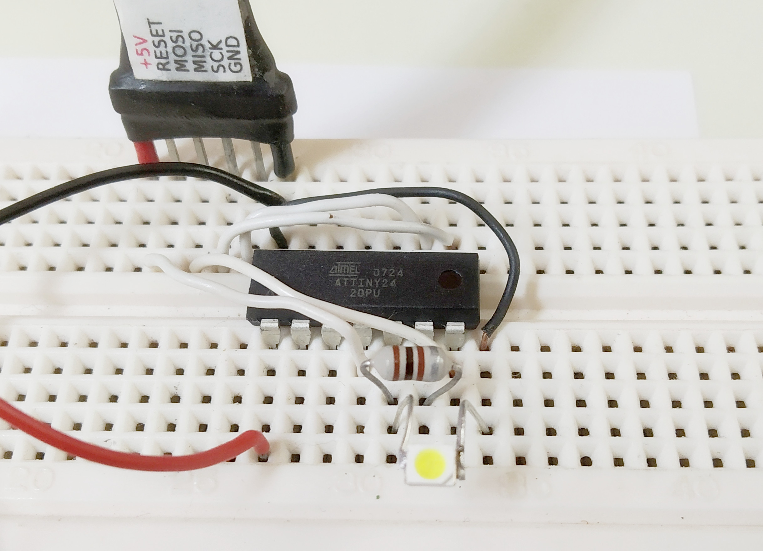
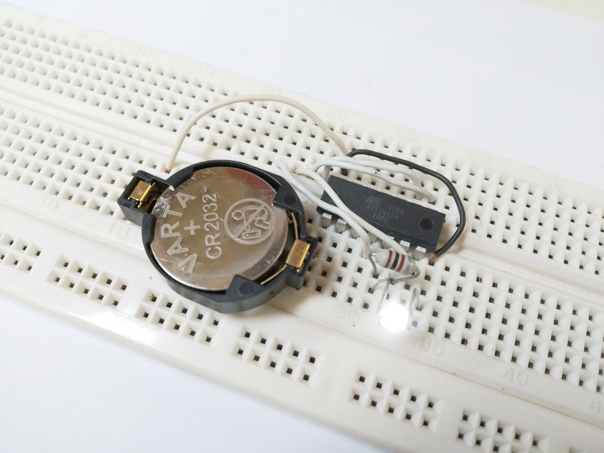
Test setup
We took a white LED in a PLCC-4 package with a forward voltage of 3.2 V and a forward current of 30 mA, soldered two wires to it, and pugged them into a breadboard. Then we added an ATiny24 AVR microcontroller from our parts bin and a 100 µH inductor (Figures 6 and 7). We connected the Reset, MOSI, MISO, SCK and GND pins of the microcontroller to our programmer. Finally, we used an adjustable lab supply to power the circuit with a supply voltage of 2 V to 3 V.
Programming the LED booster
Once all the required connections are in place, it’s time to program the ATiny24. There are various ways to output square-wave signals from a microcontroller. One option is pulse width modulation (PWM), and another is toggling the I/O pins. For the sake of simplicity, we opted for the latter approach. For our boost converter we need a switch that toggles to ground, which means the output concerned must alternately be set to open-drain and pull-down. This is done directly in a loop, without any delays. With an ATiny24 microcontroller clocked at 8 MHz, this gives an output frequency of approximately 1 MHz.
LED booster source code
#define F_CPU 8000000UL // 8 Mhz
#include <avr/io.h>
#include <util/delay.h>
int main(void)
{
unsigned long int i;
while (1)
{
PORTA |= (1<<PA7);
DDRA |= (1<<DDA7); // LED ON
for(i=0; i<=400000; i++) // Booster Loop
{
DDRB |= (1<<DDB2); // Open Drain
DDRB &= ~(1<<DDB2); // Pull down
}
PORTA &= ~(1<<PA7); // LED OFF
_delay_ms(500);
}
}
To change the default internal 1 MHz clock frequency to 8 MHz, you have to disable the CKDIV8 fuse (which is set by default). This can be done with the AVRdude program as follows:
avrdude -U lfuse:w:0xEA:m
If we now embed the booster driver loop (open-drain/pull-down loop) in a second loop that toggles the input voltage (UIN) pin, we get a classic blinker with a 'boosted' white LED (Figure 8).
Want more great Elektor content like this?
Then take out an Elektor membership today and never miss an article, project, or tutorial.
Discussion (4 comments)