
Tiny-Dice: Electronic Dice Using an ATtiny2313
Construction
Soldering: Should you be lucky enough to have a soldering iron with an adjustable bit temperature set it to around 350 to 370 °C for classic rosin-cored, lead/tin solder which produces reliable joints on DIY projects. Leadfree solder will need a temperature of around 380 to 400 °C.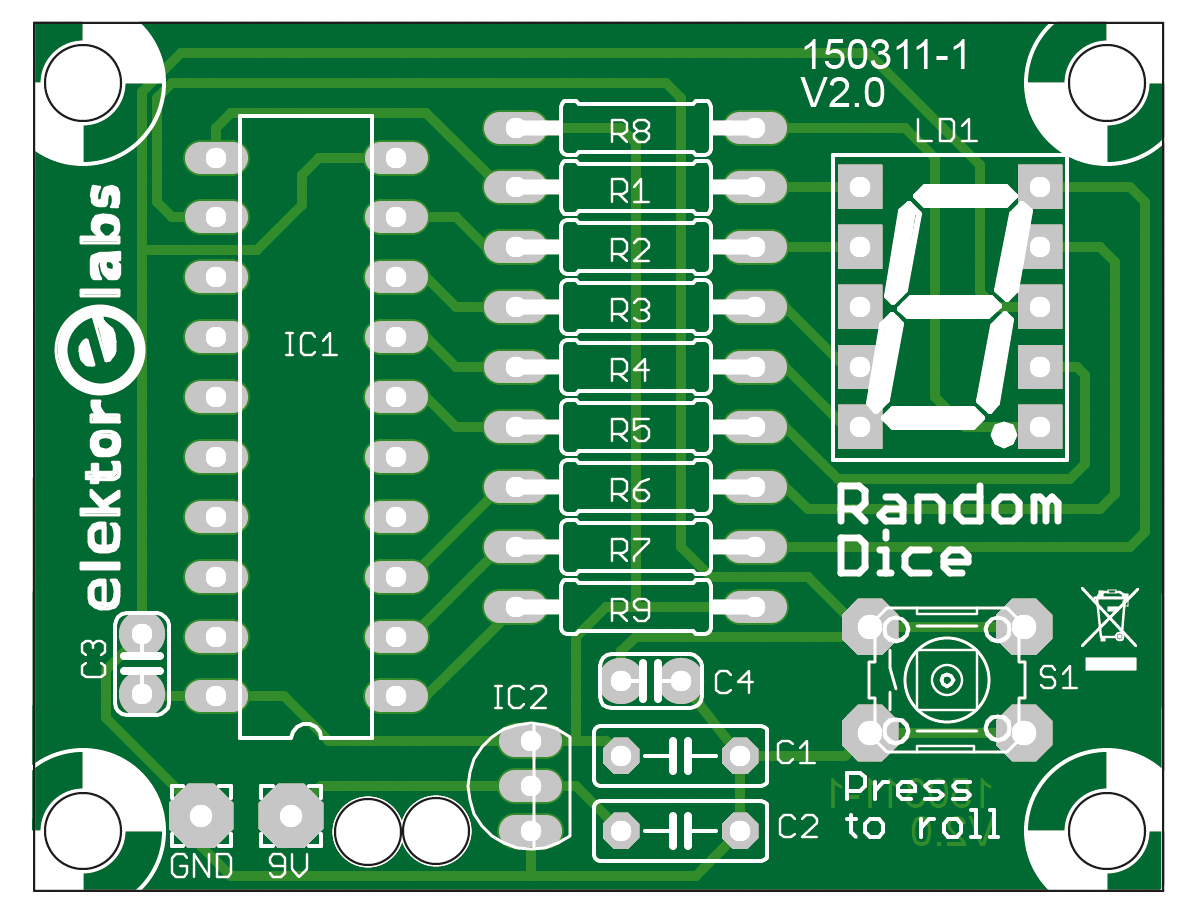
Soldering: Should you be lucky enough to have a soldering iron with an adjustable bit temperature set it to around 350 to 370 °C for classic rosin-cored, lead/tin solder which produces reliable joints on DIY projects. Leadfree solder will need a temperature of around 380 to 400 °C.
- Insert the components into the PCB from the component side. See the placement plan near the parts list.
- Make good contact with the soldering tip onto the solder pad and the component lead.
- After about half a second introduce the solder so that it contacts the pad and lead.
- When the solder melts and flows (should take around one second) remove the solder and then the iron from the joint.
- Check the joint is good.
- Clip off protruding component lead.
- Resistors (arrange them so that the color rings indicating their value can be read from left to right).
- Capacitors (check their values).
- Pushbutton.
- The IC socket (line up pin one with position 1 on the layout).
- The seven segment display (check orientation of the decimal point lead).
- IC 2 (make sure it’s correctly orientated). Don’t mount this too close to the board. Leave a gap of about 5 mm between the component base and the board surface. A component mounted close to the board can be subjected to relatively large levels of mechanical stress which may cause internal damage to the IC.
- The battery clip (feed the wires through the strain relief holes first. Black wire to the GND pad and red wire the 9 V pad).
Read full article
Hide full article
Discussion (0 comments)