
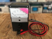
A Simple Analog ESR Meter
I was always envious of my friends analog ESR meter that allowed him to check and find bad capacitors while they were still in circuit. The particular meter he had is no longer available. It worked particularly well in finding bad electrolytic capacitors in tube amplifiers.
See also My First PCB, which describes the process of designing a PCB for the ESR Meter.
If I was to have my own such meter I would need to do some research to understand how they worked and to come up with my own version. First, what is ESR? ESR stands for the equivalent series resistance of a capacitor. ESR is frequency-dependent, temperature-dependent, and changes as components age. It’s typically important for ‘Wet’ aluminum electrolytic capacitors used in power supplies to have a low ESR. The typical method used for measuring ESR is to supply the capacitor with a known AC current (Icap) at some frequency where the capacitive reactance of the capacitor is very low so that the ESR dominates. By measuring the resulting AC voltage developed across the capacitor’s terminals (Vcap) the ESR can be determined with Ohm’s law: ESR = Vcap/Icap
Next steps will be developing PCB artwork that will make it easy for others to make their own meter. It would also be nice to come up with artwork for the meter instead of using a Post-It® Note.
Want to build a project?
Bring your design to life with the Elektor PCB Service, powered by Eurocircuits. Upload the project files and order professionally manufactured PCBs or assembled boards through a proven European production platform.
Supporting KiCad, Eagle, Gerber, and ODB++ formats, the service is suitable for everything from prototypes and validation builds to series production and volume manufacturing.
Made in Europe. Fast. Reliable. Professional.
Updates from the author