
130407-1_Platino Signal Generator
Introduction: A simple Platino-based Signal Generator is designed for not too demanding (hobbyist) applications. It is usable for applications like signal tracing, clocking of MCU circuits, audio filter & loudspeaker testing, tuning, etc.
Introduction:
A simple Platino-based Signal Generator is designed for not too demanding (hobbyist) applications. It is usable for applications like signal tracing, clocking of MCU circuits, audio filter & loudspeaker testing, tuning, etc.
A Signal generator device generates signals of different frequencies. The Platino Signal generator device uses the Elektor’s Platino board to design a real time, straight forward, non complicated design of the Signal generator. Inspired by Elektor’s AVR SDR project.
The simplified Design of the Elektor’s Platino board makes it simpler to extend its capability to develop devices of complex functionality with a few enhancements.
Specifications:
- DC Input: 18V to 20V DC
- Elektor Platino with ATMEGA1284P microcontroller.
- 20 X 4 LCD Display
- Standard BNC type connectors for outputs / Input
- One square wave output up to 10MHz, 5V and 3.3V output level switchable.
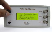
- Other outputs: Sine, Square, triangular, Sawtooth, Inv Sawtooth, Pluses, Arbitrary and Random (Noise)
- One Frequency Modulation input
Features:
- Programmable waveform output of different types of waves up to 100 KHz is given as output by the device through connector K6.
- Square wave output, 5V and 3.3V selectable DC voltage output signal through connector K5.
- Frequency Modulation input through connector K7
- All selections are done by a single rotary encoder with push button and a back button.
- The device can be powered up using an Input voltage from a standard 18V laptop power adapter
- Setup mode for Arbitrary and Clock mode.
- Normal mode for other output waveforms
- Amplitude, frequency, Offset of waveform can be changed in real time.
The Platino-based Signal Generator is divided into two major sections one the hardware and another is software, both are responsible for the stability and accuracy of Input and output. The heart of the project is the PLATINO MCU board which contains MCU ATMEGA1284P.
The Hardware consists of two sections
- Platino MCU board with LCD
- Signal Generator Add-on Board.
- Platino MCU board with LCD
The Platino board with ATMega1284P MCU is used to control and generates the signals with the add-on board. This board consists of a 20X4 line LCD display for user readout and selections of different outputs and inputs. A rotary encoder with push button is used for selecting the various waveforms. Another push button is used as a back key to navigate backwards in signal generator. This board is powered for add-on board.
- Signal Generator Add-on Board.
This board mainly consists of a convertor, amplifier and power supply components responsible for generation of different waveforms.
This board divided in to five main parts. They are as follows
- The DAC part (using a R-2R Ladder structure)
- The Amplifier part using TL082
- Level Switcher (The section made around IC CD744051 for selecting +5V & +3.3V voltage levels of output clock.)
- Frequency Modulation
- Power section.
- The DAC part (using a R-2R Ladder structure)
The DAC part is made up of a R-2R ladder, this R-2R ladder is connected to PORTA of the Atmega1284 IC of the Platino board. This ladder R1 to R16 converts the 256 Bytes values to analog which range from 0V to 5V. This voltage is then fed to the line follower of the amplifier section made up of IC1 TL082.
- The Amplifier part using TL082
This Line follower IC1 TL082 helps to separate the R-2R ladder output from that of amplifier circuit. This signal is then filtered and smoothed from high frequency components using a simple RC filter. This smoothed wave is fed to the amplifier with a gain of 4. The 5V variations are scaled to 20V variations (-10V to 10V). The potentiometer P1 used in the amplifier section is used to adjust the center point with respect to of virtual ground. The programmable waveform output is available on connector K6.
- Level Switcher
The clock’s (Square wave output) voltage level selection section is made up of IC2 CD744051 analog demultiplexer. One of the inputs of the analog demultiplexer is connected to the clock output (PB6) of the controller and the other input is connected to the voltage divider network which derives 3.3V when a 5V becomes available at the clock input pin of MCU. IC2 CD744051 connects these two voltage levels to the output according to the command selection from the controller pin (PB7). The Clock (Square wave) output is available on connector K5.
- Frequency Modulation
The connector K7 is the input connector for connecting the modulation signal. A 0V to 5V signal can be connected to K7 at a frequency up to 20 KHz. The Diode D2 is used for protecting the MCU from any high voltage damage on input pin PD0.
- Power section
The power section plays the main role in the add-on board. The 18V DC input voltage is applied to power section through connector K8. This voltage is then divided into two part of voltage from center point of voltage level using the virtual ground concept to generate positive and negative voltages.
The IC3 LM337 and IC5 LM317 voltage regulators are used to generate the virtual ground for the power section. This is required as we are using a single rail power input (18V DC) and the output of programmable waveform swings between -9V and 9V effectively. Diode D3 and D4 are used as protection diodes. Virtual ground is available at the junction of resistor R27 and R28. The input voltage is divided into two halves with the help of resistors R25, R26 and reference generator IC6 LM336. With the help of virtual ground +9V and -9V are generated for 18V input voltage.
The +9V is further send to IC4 MC7805 regulator which gives the necessary regulated voltage to the microcontroller and other components that operate on +5V supply.
In case of 20V input voltage the divided voltage with reference to virtual ground will swing between -10 and +10V.
Software:
The software for the project is written in BASCOM AVR for ATMEGA1284P microcontroller. The Platino board is used for further development of the project. The software part is divided into two main sections discussed below.
Normal Mode:
In Normal Mode one can select various output waveform signals and for each signal one can change the parameters like Amplitude, frequency, offset etc and view the output in real time using the rotary encoder and the back push button on the Platino board.
In Normal mode, In addition to normal signal mode an additional FM mode is available, in which a Square wave is generated according to the input value. If a high is detected on PD) pin of MCU then the output will be 125 KHz + 50 Hz and if a low is detected then the output will be 125 KHz-50 Hz.
Setup Mode:
In setup mode there are two options:
- Arbitrary mode: in this mode the user can enter different values according to his/her choice. Then he/she can select the arbitrary signal from the Normal Mode and generate a custom signals.
- Clock mode: In this mode one can select the frequency of the clock that is additionally produced side by side with the main output signal.
The frequency generation is done on the basis of time indexing, that is a timer value is set on the basis of the frequency selected. This timer value is then used as an index to find the frequency to be outputted from the look up table. The timer value is also used to determine the speed and time period of the signal to be generated
Building the Prototype:
First build the Platino with its LCD, rotary encoder with pushbutton and an additional push button (back button), ATMEGA1284P MCU and all other components, then ‘jumper’ it as shown in Table 2
The add-on board that consists of the main circuitry for the signal generator that is connected to the Platino board via connectors K2, K2, K3 and K4. The Add-on board of signal generator is so designed to fix exactly to the back of Platino with the help of connectors. Bolpa enclosure is used to fix everything inside which includes the Platino board with 20 X 4 LCD, Rotary encoder with pushbutton.
Testing:
The device is powered up through connector K8 with 18V DC adapter. Before selecting the wave to be generated we need to make the voltage across K6 zero by adjusting the Potentiometer P1. This is a onetime adjustment required when you power on the unit for the first time. The type of wave to be generated is then selected in Normal mode with the help of the rotary encoder. The device allows you to change the wave parameters and generate the wave in real time. The Additional push button is used as back key to go back from current screen.
The clock output voltage can be set to either 5V or 3.3 V in the Clock mode tab under setup mode.
Table 1. Microcontroller Pins Usage
Pin designation Function
PORTA: Connected to R-2R DAC ladder structure
PB5: LCD backlight control
PB3: Back button
PB6: Clock output pin
PB7: Digital pin for clock voltage selection
PC0–PC2: Encoder with pushbutton
PD0: FM modulation Digital pin
Table 2. Jumper settings on Platino
JP4:PB0
JP5:PB1
JP6:PB2
JP7:PB3
JP11:PB7
JP12:PB6
In the Elektor shop <platino-signal-generator-130407-1> a bundle with
- 1xplatino signal generator (130407-1)
- 1xBopla Unimas 160 (050176-74)
- 1x4x20 LCD (120061-73)
- 1xPlatino PCB (100892)
- 1xPlatino Signal Generator Programmed Controller (130407-41)
Want to build a project?
Bring your design to life with the Elektor PCB Service, powered by Eurocircuits. Upload the project files and order professionally manufactured PCBs or assembled boards through a proven European production platform.
Supporting KiCad, Eagle, Gerber, and ODB++ formats, the service is suitable for everything from prototypes and validation builds to series production and volume manufacturing.
Made in Europe. Fast. Reliable. Professional.
Discussion (2 comments)