
Altium Designer 20 and the Altium 365 Platform
on
Some time ago, Elektor started using Altium Designer 6, after working for years with Cadence OrCAD for schematics and Ultiboard for PCB design. After our initial investment, we skipped several subsequent updates, until Altium Designer 14 was released.
Software updates can be time consuming, but in this case everything worked fine. Most — if not all — settings were automatically copied into this newer version and the user interface didn’t change much, so we could start using Altium Designer 14 (almost) immediately. As I recall, for the designs we normally made in the Elektor Lab, there weren’t that many significant changes or new features that we really needed, actually.
Recently, we updated to Altium Designer 20, and frankly, I didn’t expect to get as excited about this new version as I am now. Read on to learn exactly why!
Getting started with a new version
When we upgraded from Altium Designer 14 to Altium Designer 20, the change initially seemed to be a lot bigger, which is largely due to the new, dark GUI...quite a difference from the light backgrounds we were used to. Thankfully, you get used to it very quickly.
This isn’t to say that nothing else has changed in Altium Designer 20, but as with the previous upgrade, the settings were automatically imported and you can work with the standard operations just as with Altium Designer 14. It is a relief that the familiar key combinations (hotkeys) still have the same functionality; other software manufacturers could learn something from this. The older version still keeps working and it is quite reassuring that you can, if necessary, go back to a more familiar trusted version.
Altium Designer is an enormously extensive and powerful PCB CAD tool, which offers far more functionality than is needed for the designs that Elektor usually publishes. One of the reasons for choosing Altium Designer 6 was because the schematic editor offers graphical features (such as selecting different line thicknesses and fonts) that are missing in other CAD packages, so that the schematics could immediately be drawn and published in the trusted Elektor style. Previously, all schematics were redrawn by our graphical department and the result had to be “manually” checked with the original. The introduction of Altium Designer didn’t mean that we never used other CAD software, as we do when working on projects from external designers, but that illustrated how user-friendly Altium Designer is, especially when it comes to creation and maintenance of custom-made schematic and PCB libraries.
The new features of Altium Designer 20 are summarized on their website, so it doesn’t really make sense to discuss them here (plus, we’ll be migrating to Altium Designer 21 soon). Altium has long since ported the software to 64-bit architecture, which improves the performance especially for larger designs. For Elektor, it was great that Altium Designer could already import Autodesk Eagle CAD files because many designs from external authors were developed with this design package, and in Altium Designer 20 imports from KiCad are also supported. But it’s the availability of Altium 365 that really makes everything fall into place in the best way possible.
Altium 365 is the world’s first cloud platform for PCB design and realization. If you’re invited to join a team, you only have to provide a password for logging on; no registration is required. I had never seen something like this before, and it is absolutely fantastic.
All people involved in a project can now follow your work from the start, at every stage of the design, and indicate in good time what can or must be changed, without the time-consuming process of making and mailing screenshots, exporting your design data to formats that can be viewed by everyone involved and keeping those files up to date.
Putting your project on the cloud
To collaborate on the cloud using Altium Designer 20 and Altium 365, start by opening the project you want to share. In Figure 1, in the upper right corner, the online workspace Elektor International Media BV is active and open.
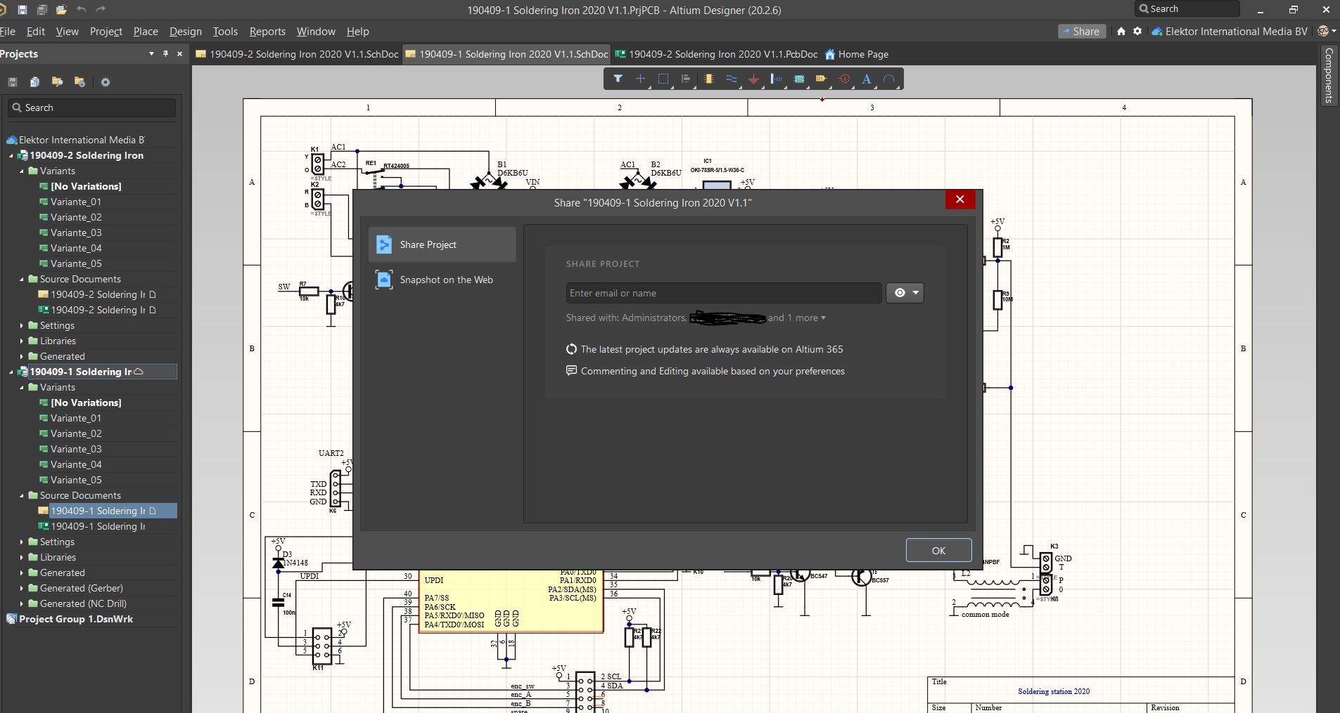
Click the Share button next to this workspace to open the dialog window shown. Here you can enter the email addresses of the stakeholders, the people you want to share your project with.
Clicking the button with the eye-shaped icon next to this input field is used to select if this participant can either view or even edit the design files. Licensed Altium Designer 20 users have editing rights; viewing requires no additional software except for a web browser.
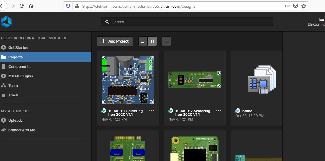
Designated team members receive an email containing a link to log on to your workspace and access the project design files. After logging on, the screen in Figure 2 is presented, clicking on one of the shared projects presents a screen like shown in Figure 3.
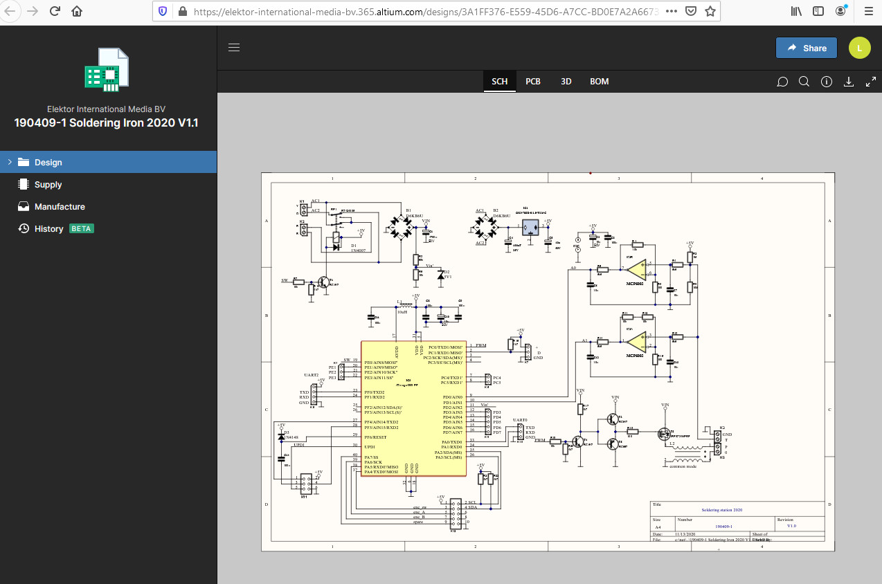
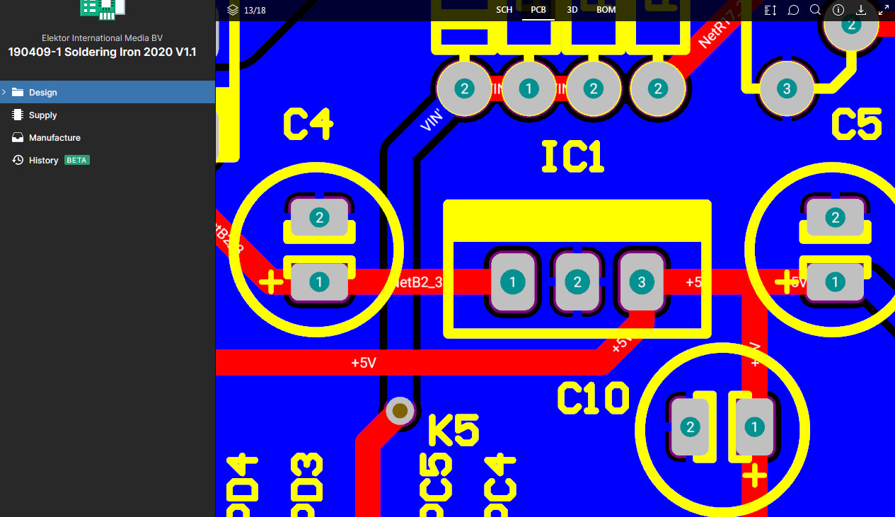
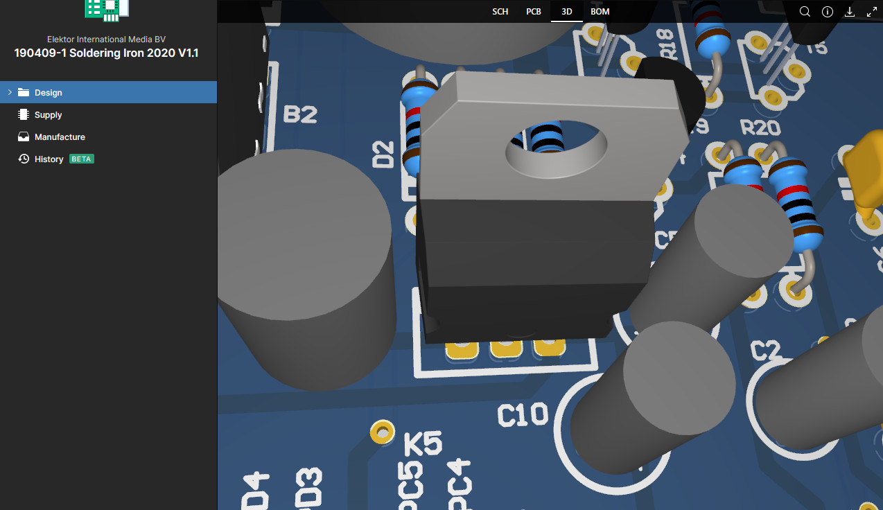
At every stage in the design process, the most recent version of the schematic, PCB layout, 3D view and BOM can be viewed (tabs SCH, PCB, 3D and BOM respectively), which is already a great step forward when you’re used to exporting files after every update. But there is much, much more than just static views!
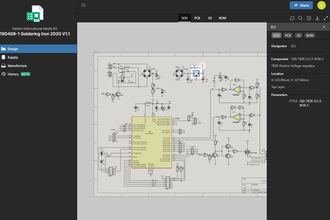
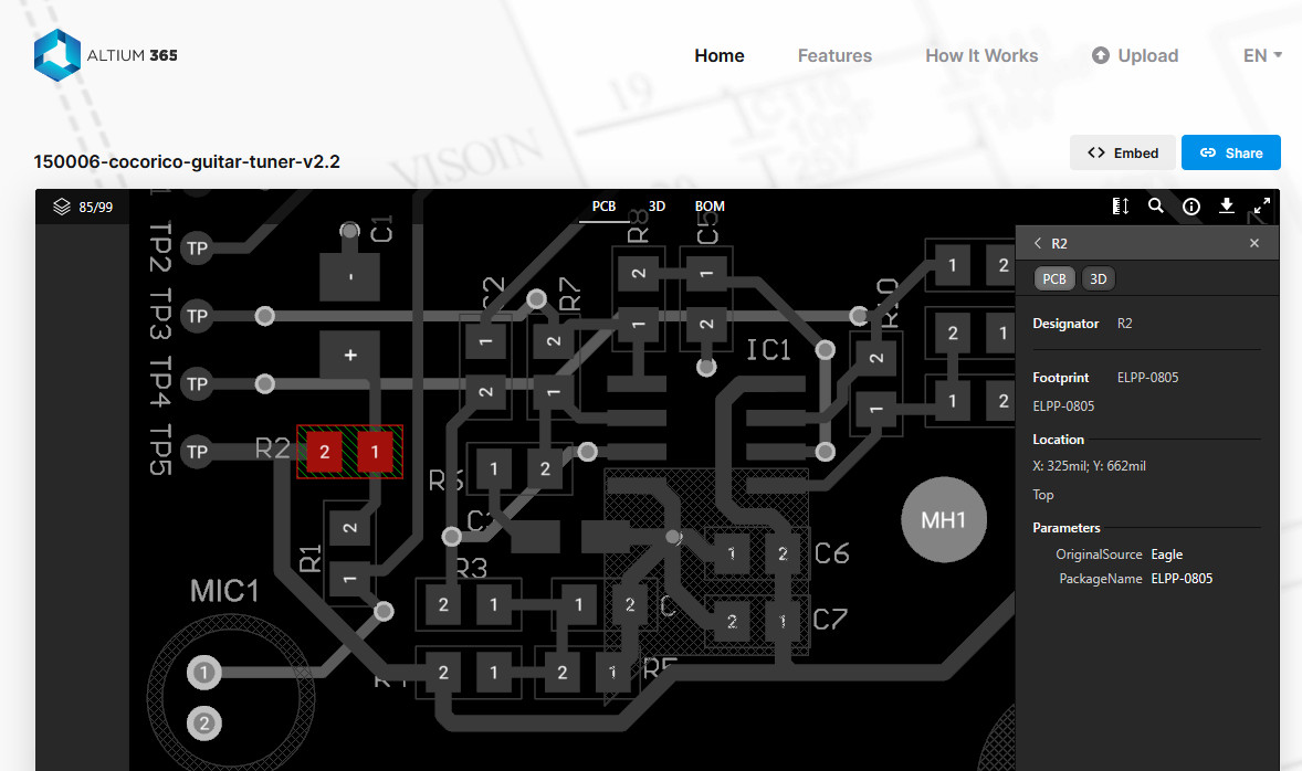
Altium 365 is context-sensitive, so cross-probing between all views is very easy. For example, when you click a component in the schematic diagram, an info panel with its schematic diagram data will be displayed at the right side of the screen. Clicking on PCB, 3D or BOM shows its position on the PCB, its 3D view and component list data respectively (Figure 4).
You can also start with selecting a component in any other view (e.g., click a component’s designator in the BOM and see where it is on the PCB layout, which comes in handy when assembling your prototype).
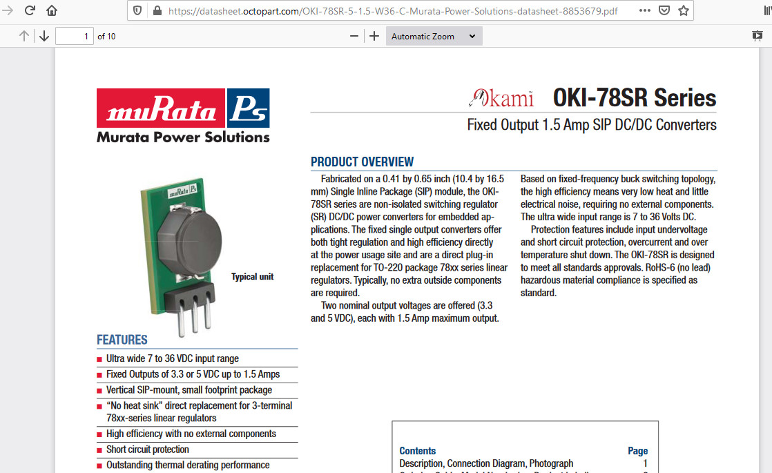
If you think that’s great, try clicking the component’s name in the BOM and your browser will display the part on Octopart (Figure 5), offering links to the datasheet and suppliers.
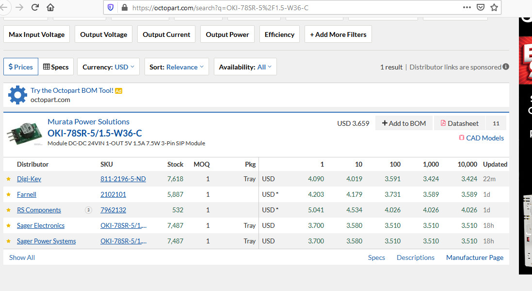
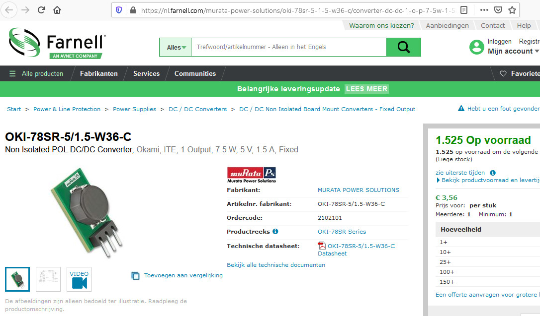
Octopart is a powerful search engine that makes it fast and easy to compare millions of components, find technical information, quickly make component selection decisions, and purchase parts from thousands of distributors.
In the schematic and PCB view, any participant can add comments by clicking the button with the speech balloon icon, marking an area and typing the question and/or remark (Figure 6).
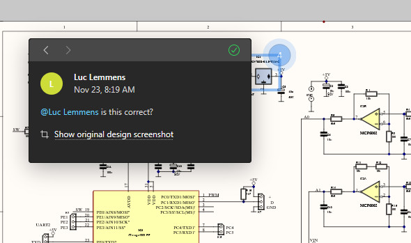
When the name of a team member is added to the text (with the preceding “@”), the person concerned will receive an email notifying him or her of the need to take action. When multiple Altium Designer users are involved in the project, version control is available to keep track of the latest changes and history of the design.
Not just for Altium Designer users
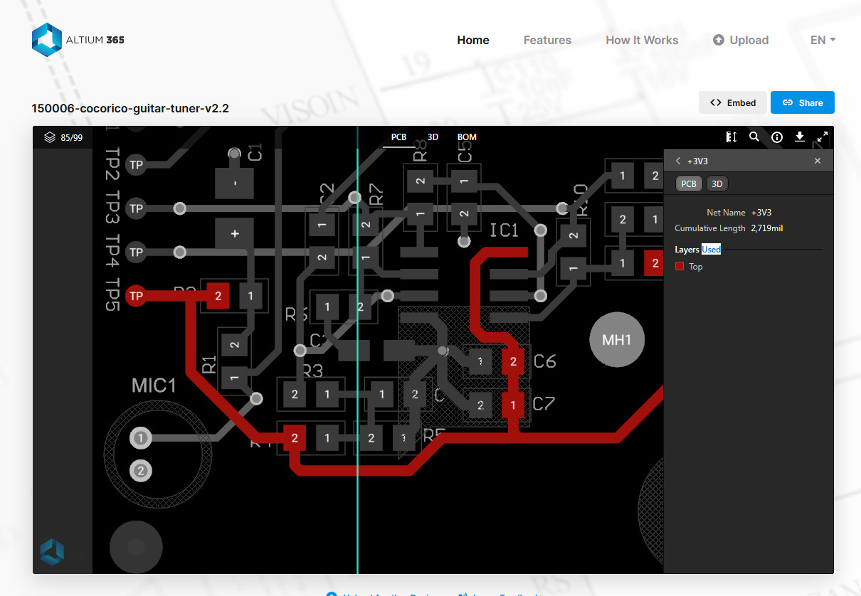
If you use PCB design software other than Altium Designer, you can still benefit from Altium 365.The online viewer tool not only supports viewing and sharing of Gerber data, but also of schematics and PCB layouts designed with a variety of PCB software applications, including Autodesk Eagle and KiCad.
The viewer tool’s functionality is a bit more limited than when using Altium Designer. After you have uploaded files to the viewer, you can send a link to people you want to share this data with and this link remains valid for 48 hours. With this approach, you only share snapshots and after every change you will have to upload and share new data. The data is not in a workspace that contains design files that are always automatically up to date, but this is already an enormous improvement because you can give other people involved in your project a much deeper and more detailed insight into the design data than, for example, in a PDF or screenshot. To illustrate, Figure 7 shows details of an Autodesk Eagle PCB design in the online viewer, where the user can select nets or components to look at them more closely.
As a longtime Altium Designer user, I am absolutely thrilled by Altium 365. This is really what we needed and what we had been looking for — for years now. Altium Designer may not necessarily be the most affordable schematic/PCB design solution, but considering the time that can be saved by including all stakeholders in the development at a very early stage by using this CAD software combined with Altium 365, even stingiest boss can hopefully see the benefits of investing in an Altium Designer license.
Want more great Elektor content like this?
Take out an Elektor membership today and never miss an article, project, or tutorial.
Discussion (3 comments)