
Cat repeller
How to chase away the cat of your neighbours that uses your garden as a toilet ? Or you can use this project as a practical joke to fool a friend !
Introduction
This little project was started because i wanted to chase away a cat that was stalking my 2 cats and even sneaked into our house via the cat-door. When that happens, my 2 cats defend their home territory and started a fight, making a lot of noise and waking us up in the middle of the night a few times a week. Of course i didn't want to let that happen and started thinking about an "animal-friendly" way to prevent the cat from approaching the house.
Of course there are all kind of cat-door systems that allow access based on RFID tags that are embedded in a cat-collar.
There are ultrasonic cat-repellers, but those don't seem to work for any cat or only work temporarily because the cat gets used to the annoying sound. There are also electric fence applications to scare away cats or to keep your own cats within your property.
But most cats don't like to get wet and certainly not by a water jet coming from a garden hose. The hissing sound of the water jet already scares them, but they hate getting hit by a water jet. So that was the way to go.
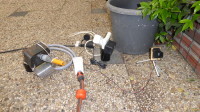
So i designed a small system using a PIR motion sensor module and some electronics to control an electric water valve. The electric water valve is connected between a garden hose and a spray mouth, so we can control if water is passed to the spray mouth. The spray mouth can be pointed to any direction. The viewing angle of a PIR sensor mostly is pretty wide. To make sure that we hit the cat with the water jet from the spray mouth, the viewing angle of the PIR motion sensor needs to be decreased. This is done by putting the PIR sensor in a short tube, so it can only see motion right in front of the sensor. When the PIR motion sensor and the spray mouth are positioned properly, the water jet will hit anything that passes the field of vision of the PIR motion sensor.
Circuit
When the PIR motion sensor (top left) detects motion, we want the water valve (top right) to be activated long enough to chase the cat away. The output of the motion sensor remains high for maximum half a second, so we need to stretch this pulse to about 1 or 2 seconds, so the water jet lasts long enough. Therefore we use a one shot (monostable multivibrator). To design a one-shot, you can use a 555 timer chip, a CMOS 4528/38 or a comparator to do the job, but here we've chosen to use an OPAMP, just to try something different than usual.
So U1A is configured as a one shot (monostable) timer. The output of U1A is connected to N-MOSFET Q1. When the output of U1A goes high, Q1 conducts and the water valve will open, so water from the garden hose is passed to the spray mouth.
R1 and R4 provide positive feedback, making the non-inverting input of the OPAMP more positive when the output of the OPAMP goes high. The input of the one-shot is connected to the non-inverting input via diode D2. The inverting input is connected to the output via D3 so when the OPAMP output is low, the inverting input is pulled low by the diode when the voltage on the inverting input is higher than one diode drop. R2 and C1 form a RC circuit and determine the time that the one-shot output is high.
Let's check what happens when we power the circuit : At power on, C1 is fully discharged so the voltage over C1 = 0V. That means that the inverting input of U1A is 0V. Because U1A is not a rail to rail output, it's output won't be 0V but somewhere close to 1V. That means that the non-inverting input will be around 0.5V. So at power on, the voltage at the non-inverting input is higher than the voltage on the inverting input, resulting in the OPAMP output swinging to the positive rail. The voltage at the non-inverting input will now be equal to the OPAMP output voltage divided by 2 (R1 is equal to R4). Meanwhile C1 is charging to the positive rail via R2. At the moment that the voltage over C1 exceeds the voltage at the non-inverting input, the OPAMP output will swing to ground and D3 will discharge C1 quickly to about 1V + 0.6V = 1.6V. The voltage at the non-inverting input is about 1V / 2 = 0.5V, which is lower than the voltage on the inverting input. So the OPAMP output will stay low.
In short, at power on, the output of U1A first goes high for about 2.5 seconds and then goes low and stays low. This is undesired behaviour, because that would mean that the water valve is opened for 2.5 seconds at power on. Additionally we want the cat repeller to stay inactive for some time after power on, so we don't get wet ourselves while getting out of field of view of the motion sensor. To achieve this, we added N-MOSFET Q3, that short circuits the non-inverting input of OPAMP U1A to ground for a certain time at power on, determined by RC circuit C3 and R10. Short-circuiting the non-inverting input to ground disables the one-shot, so any input pulse from the PIR motion sensor is ignored and the water valve remains closed when powering on.
With the given component values, the cat repeller (water valve) will stay inactive for about 25 seconds after power on, provided that C3 is fully discharged before powering on again. Q4 is added so a green LED D8 tells us when the repeller is inactive. At power on, the green LED D8 will be on together with the red LED D7 that is connected directly to the power supply voltage. The green LED will remain on for about 25 seconds. When the green LED goes off, the cat repeller is active.
Because i also wanted to have an indication if the cat repeller had been active during the night, i added an extra circuit composed of a bistable multivibrator (flip flop) that is reset when the cat repeller is powered on and that is set when the cat repeller is active and has detected motion/sprayed water. Especially when using the cat repeller in grass or when it has been raining during the night, it is hard to see if the cat repeller has been triggered.
OPAMP 1B is configured as a bistable multivibrator (flip flop) and is used to indicate if the cat repeller has been triggered. So if any motion is detected and the water valve was opened, the flip flop is set and the blue LED D9 comes on to indicate that the cat repeller has been triggered. Because the OPAMP can not source or sink enough current to control a LED, transistor Q2 is used as a buffer to provide the necessary current for LED D9. The inverting input of U1B is the "reset" input of the flip flop and the non-inverting input is the "set" input. The inverting (reset) input of U1B is set to half the power supply by R8 and R11. C2 is used to reset the flip flop at power on, so the output of U1B is low after power on. The flip flop is set when the output of U1A goes high, because then D4 will conduct and will raise the voltage on the non-inverting input above the voltage on the inverting input. The output of U1B will swing to the positive supply rail and D5 and D6 will take care that the voltage at the non-inverting input will remain high, even when the output of U1A goes low again. Due to D5 and D6, U1B remains latched into the "set" state once it is set, and the blue LED D9 remains on.
Why 2 diodes D5 and D6 ? Well, in retrospect 1 diode will also work fine for this circuit. This is because we don't use a diode connected to the "reset" input of the flip flop (inverting input of U1B) to reset the flip flop. When we would want to use the "reset" input and make it high via a diode, then we would need 2 diodes to make sure that the voltage at the inverting input can rise above the voltage at the non-inverting input, to be able to reset the flip flop. Since we don't use the "reset" input, we would get away with only 1 diode.
See also : https://www.edn.com/design/other/4373768/Use-an-op-amp-as-a-set-reset-flip-flop
So the cat repeller has 3 indicator LED's :
The housing of the water valve and PCB is 3D printed using transparent filament so the red, green and blue LEDs can shine through the housing. Since i only use the cat repeller at night, i can clearly see the LEDs shining through the semi-transparent housing.
This little project was started because i wanted to chase away a cat that was stalking my 2 cats and even sneaked into our house via the cat-door. When that happens, my 2 cats defend their home territory and started a fight, making a lot of noise and waking us up in the middle of the night a few times a week. Of course i didn't want to let that happen and started thinking about an "animal-friendly" way to prevent the cat from approaching the house.
Of course there are all kind of cat-door systems that allow access based on RFID tags that are embedded in a cat-collar.
There are ultrasonic cat-repellers, but those don't seem to work for any cat or only work temporarily because the cat gets used to the annoying sound. There are also electric fence applications to scare away cats or to keep your own cats within your property.
But most cats don't like to get wet and certainly not by a water jet coming from a garden hose. The hissing sound of the water jet already scares them, but they hate getting hit by a water jet. So that was the way to go.
So i designed a small system using a PIR motion sensor module and some electronics to control an electric water valve. The electric water valve is connected between a garden hose and a spray mouth, so we can control if water is passed to the spray mouth. The spray mouth can be pointed to any direction. The viewing angle of a PIR sensor mostly is pretty wide. To make sure that we hit the cat with the water jet from the spray mouth, the viewing angle of the PIR motion sensor needs to be decreased. This is done by putting the PIR sensor in a short tube, so it can only see motion right in front of the sensor. When the PIR motion sensor and the spray mouth are positioned properly, the water jet will hit anything that passes the field of vision of the PIR motion sensor.
Circuit
When the PIR motion sensor (top left) detects motion, we want the water valve (top right) to be activated long enough to chase the cat away. The output of the motion sensor remains high for maximum half a second, so we need to stretch this pulse to about 1 or 2 seconds, so the water jet lasts long enough. Therefore we use a one shot (monostable multivibrator). To design a one-shot, you can use a 555 timer chip, a CMOS 4528/38 or a comparator to do the job, but here we've chosen to use an OPAMP, just to try something different than usual.
So U1A is configured as a one shot (monostable) timer. The output of U1A is connected to N-MOSFET Q1. When the output of U1A goes high, Q1 conducts and the water valve will open, so water from the garden hose is passed to the spray mouth.
R1 and R4 provide positive feedback, making the non-inverting input of the OPAMP more positive when the output of the OPAMP goes high. The input of the one-shot is connected to the non-inverting input via diode D2. The inverting input is connected to the output via D3 so when the OPAMP output is low, the inverting input is pulled low by the diode when the voltage on the inverting input is higher than one diode drop. R2 and C1 form a RC circuit and determine the time that the one-shot output is high.
Let's check what happens when we power the circuit : At power on, C1 is fully discharged so the voltage over C1 = 0V. That means that the inverting input of U1A is 0V. Because U1A is not a rail to rail output, it's output won't be 0V but somewhere close to 1V. That means that the non-inverting input will be around 0.5V. So at power on, the voltage at the non-inverting input is higher than the voltage on the inverting input, resulting in the OPAMP output swinging to the positive rail. The voltage at the non-inverting input will now be equal to the OPAMP output voltage divided by 2 (R1 is equal to R4). Meanwhile C1 is charging to the positive rail via R2. At the moment that the voltage over C1 exceeds the voltage at the non-inverting input, the OPAMP output will swing to ground and D3 will discharge C1 quickly to about 1V + 0.6V = 1.6V. The voltage at the non-inverting input is about 1V / 2 = 0.5V, which is lower than the voltage on the inverting input. So the OPAMP output will stay low.
In short, at power on, the output of U1A first goes high for about 2.5 seconds and then goes low and stays low. This is undesired behaviour, because that would mean that the water valve is opened for 2.5 seconds at power on. Additionally we want the cat repeller to stay inactive for some time after power on, so we don't get wet ourselves while getting out of field of view of the motion sensor. To achieve this, we added N-MOSFET Q3, that short circuits the non-inverting input of OPAMP U1A to ground for a certain time at power on, determined by RC circuit C3 and R10. Short-circuiting the non-inverting input to ground disables the one-shot, so any input pulse from the PIR motion sensor is ignored and the water valve remains closed when powering on.
With the given component values, the cat repeller (water valve) will stay inactive for about 25 seconds after power on, provided that C3 is fully discharged before powering on again. Q4 is added so a green LED D8 tells us when the repeller is inactive. At power on, the green LED D8 will be on together with the red LED D7 that is connected directly to the power supply voltage. The green LED will remain on for about 25 seconds. When the green LED goes off, the cat repeller is active.
Because i also wanted to have an indication if the cat repeller had been active during the night, i added an extra circuit composed of a bistable multivibrator (flip flop) that is reset when the cat repeller is powered on and that is set when the cat repeller is active and has detected motion/sprayed water. Especially when using the cat repeller in grass or when it has been raining during the night, it is hard to see if the cat repeller has been triggered.
OPAMP 1B is configured as a bistable multivibrator (flip flop) and is used to indicate if the cat repeller has been triggered. So if any motion is detected and the water valve was opened, the flip flop is set and the blue LED D9 comes on to indicate that the cat repeller has been triggered. Because the OPAMP can not source or sink enough current to control a LED, transistor Q2 is used as a buffer to provide the necessary current for LED D9. The inverting input of U1B is the "reset" input of the flip flop and the non-inverting input is the "set" input. The inverting (reset) input of U1B is set to half the power supply by R8 and R11. C2 is used to reset the flip flop at power on, so the output of U1B is low after power on. The flip flop is set when the output of U1A goes high, because then D4 will conduct and will raise the voltage on the non-inverting input above the voltage on the inverting input. The output of U1B will swing to the positive supply rail and D5 and D6 will take care that the voltage at the non-inverting input will remain high, even when the output of U1A goes low again. Due to D5 and D6, U1B remains latched into the "set" state once it is set, and the blue LED D9 remains on.
Why 2 diodes D5 and D6 ? Well, in retrospect 1 diode will also work fine for this circuit. This is because we don't use a diode connected to the "reset" input of the flip flop (inverting input of U1B) to reset the flip flop. When we would want to use the "reset" input and make it high via a diode, then we would need 2 diodes to make sure that the voltage at the inverting input can rise above the voltage at the non-inverting input, to be able to reset the flip flop. Since we don't use the "reset" input, we would get away with only 1 diode.
See also : https://www.edn.com/design/other/4373768/Use-an-op-amp-as-a-set-reset-flip-flop
So the cat repeller has 3 indicator LED's :
- D7 = red LED = When the red LED is on, the cat repeller is powered.
- D8 = green LED = The green LED will come on for about 25 seconds after power on. As long as this green LED is on, the cat repeller is disabled and will not react to any motion. When the green LED is off, the cat repeller is armed and will react to motion.
- D9 = blue LED = When this LED is on, the means that the cat repeller has detected motion and has been active.
The housing of the water valve and PCB is 3D printed using transparent filament so the red, green and blue LEDs can shine through the housing. Since i only use the cat repeller at night, i can clearly see the LEDs shining through the semi-transparent housing.
Want to build a project?
Bring your design to life with the Elektor PCB Service, powered by Eurocircuits. Upload the project files and order professionally manufactured PCBs or assembled boards through a proven European production platform.
Supporting KiCad, Eagle, Gerber, and ODB++ formats, the service is suitable for everything from prototypes and validation builds to series production and volume manufacturing.
Made in Europe. Fast. Reliable. Professional.
Discussion (1 comment)