Tired of hunting short-circuits with a magnifying glass? This clever circuit makes locating a PCB short fast and frustration-free. Build a similar circuit to track down faults with ease.
Tired of hunting short-circuits with a magnifying glass? This clever circuit makes locating a PCB short fast and frustration-free. Build a similar circuit to track down faults with ease.
Principle of Operation
As most engineers know, unexpected short-circuits have a way of showing up exactly where — and when — they are least wanted. If you're tired of squinting at your PCB through a magnifying glass, Ton Giesberts’s practical circuit takes the hassle out of tracking down a PCB short.
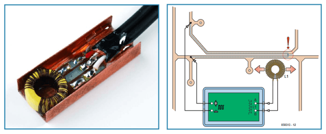
The working principle of the circuit (Elektor 6/2006) is straightforward. When a PCB short is present, unwanted current flows in its vicinity — a fact this design exploits. By directing a current into the suspected area of the PCB, a magnetic field is produced, which can then be detected. The current — and thus the magnetic field — extends right up to the short. Once the field is sensed, the short-circuit finder emits an audible tone.
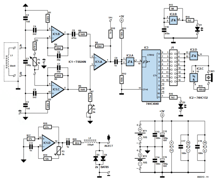
PCB short finder schematic
As you can see, Giesberts divided the schematic into two parts. One part provides the generation of the test signal. The other part detects and amplifies the picked-up signal. He explains:
"The signal is picked up by coil L1 that we wind ourselves. To make the detection more sensitive, we selected a frequency that is just outside the audible frequency range (about 29 kHz). To make this frequency audible, the signal that is amplified by IC1a through IC1c, is routed via a digital Schmitt trigger (IC2a, a 74HC132) to a divider IC3 (74HC4040). P1 adjusts the gain. The first eight outputs are available on the outside. You select the frequency of the sound that can be reproduced well with an AC-buzzer using jumper JP1. To maximise the volume of the sound a little bridge amplifier is made with two gates from IC2 (IC2c and IC2d). The buzzer is connected to the pins that are marked ‘BZ1’. R15 limits the current to a safe value (< 20 mA)."
When assembling the circuit in an enclosure, Giesberts explains, you must be sure to account for a few things: the PCB size, the AC buzzer, battery holders, LED placement, and the double-pole on/off switch.
The design in use.
PCB Short Finder Project
The article, “Find the Fault: Audible Short-Circuit Finder,” appeared in Elektor June 2006. You can read the article free during the two weeks following the publication of this post. Once you begin a project of your own, you can share your progress on the Elektor Labs platform!
Editor's Note: This article was first published in a 2006 edition of ElektorMag. Due to the project’s age, some of the components, PCBs, products, or links might not be available. Nevertheless, we think the content is a helpful resource, and we believe it will inspire you to begin new electronics projects at your workbench.
Subscribe
Tag alert: Subscribe to the tag Circuits & Circuit Design and you will receive an e-mail as soon as a new item about it is published on our website!
Elektor Magazine has been one of the leading sources of information on electronics for engineers, designers, start-ups and companies for 65 years. Our magazine is powered by an active community of electronics engineers – from students to professionals – who are passionate about designing and sharing innovative ideas.
For them, we publish hundreds of items a year, in formats such as articles, videos, webinars, and other learning formats. Our mission is to share knowledge in every possible way and inspire readers with the latest developments within the electrical engineering sector.
Thank you for your vote!
Leave further comments in the fields below.
Thank you for your vote!
If you wish to leave a comment with your rating, please first use the login below. If not, just close this window.


Discussion (0 comments)