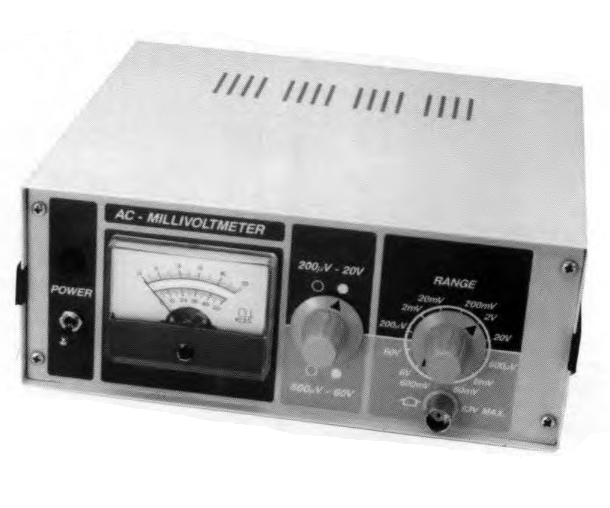
Check out this interesting wideband AC millivoltmeter circuit from 1990. The simple design features 12 ranges, decent accuracy, 200 µV accuracy, and a frequency range from 20 Hz to more than 2 MHz. Take a look.
While doing some research in the archives at the start of the new year, we came across this interesting wideband AC millivoltmeter circuit from 1990. The design featured 12 ranges, decent accuracy, 200 µV accuracy, and a frequency range from 20 Hz to more than 2 MHz.
AC Millivoltmeter Project
Why an AC millivoltmeter? The designer, T. Giffard, explained:
"Compared to the digital multimeter, the AC millivoltmeter offers a much greater bandwidth. Although hard to beat for DC measurements, most DMMs have a frequency range of just 400 Hz which makes them really unsuitable even for signal tracing and frequency response measurements in AF amplifiers. By contrast, the AC millivoltmeter has a bandwidth of 20 Hz to 2 MHz."
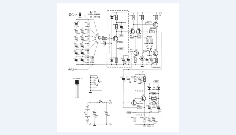
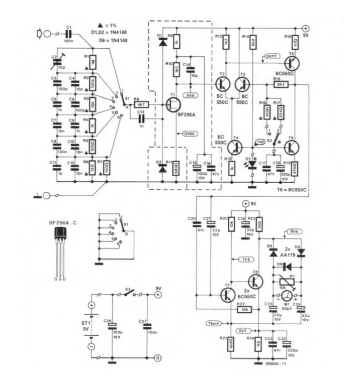
Circuit diagram of the wideband millivoltmeter.
The Circuit
Since the instrument measures AC voltage only, off-set and drift are not normally problems in the amplifier stages. This means that integrated differential amplifiers in the form of operational amplifiers are not needed, and may be replaced by a circuit based on discrete transistors. The final version of this circuit was found to offer good stability at a reasonable bandwidth by virtue of the accurately compensated voltage divider at the input, and a PCB design that prevents problems with wiring capacitance by accommodating the range switch on the printed-circuit board.
"Depending on the position of S2 in the measurement amplifier, the AC voltage at the gate of FET T1 that results in full-scale deflection of the meter is either 0.2 mV or 0.6 mV," Giffard noted. "The gate of the FET forms a very high impedance so that the voltage divider is hardly loaded. Components D1-D2 and R8 protect the gate against overvoltage. Diodes D1 and D2 conduct at gate voltages of about +9.6 V and -0.6 V respectively and afford protection to about 50 V in the 0.2 mV range. Capacitor C13 prevents R8 and its associated stray capacitance (the FET, the diodes and the relevant PCB tracks) forming a low-pass filter that would limit the bandwidth of the millivoltmeter."
The AC millivoltmeter
The AC Millivoltmeter Project
The article, “Simple AC Millivoltmeter,” appeared in Elektor January 1990. You can read the article free during the two weeks following the publication of this post. If you start a similar project, make sure you post it on the Elektor Labs platform! Editor's Note: The article first appeared in a 1990 edition of ElektorMag. Some of the components, products, PCBs, and/or links might not be available at this time. Still, we feel this educational content is valuable, and we hope it will inspire you to start new projects of your own.
Subscribe
Tag alert: Subscribe to the tag Circuits & Circuit Design and you will receive an e-mail as soon as a new item about it is published on our website!
Elektor Magazine has been one of the leading sources of information on electronics for engineers, designers, start-ups and companies for 65 years. Our magazine is powered by an active community of electronics engineers – from students to professionals – who are passionate about designing and sharing innovative ideas.
For them, we publish hundreds of items a year, in formats such as articles, videos, webinars, and other learning formats. Our mission is to share knowledge in every possible way and inspire readers with the latest developments within the electrical engineering sector.
Thank you for your vote!
Leave further comments in the fields below.
Thank you for your vote!
If you wish to leave a comment with your rating, please first use the login below. If not, just close this window.


Discussion (0 comments)