Measuring a specific point (node) in an RF circuit with a regular oscilloscope probe can disrupt the circuit's performance, even when the probe is set to a less intrusive mode. A solution is a specialized probe designed to minimize interference. Check out this 1-GHz active probe design.
Measuring a specific point (node) in an RF circuit with a regular oscilloscope probe can disrupt the circuit's performance, even when the probe is set to a less intrusive mode. A solution is a specialized probe designed to minimize interference. Check out this 1-GHz active probe design.
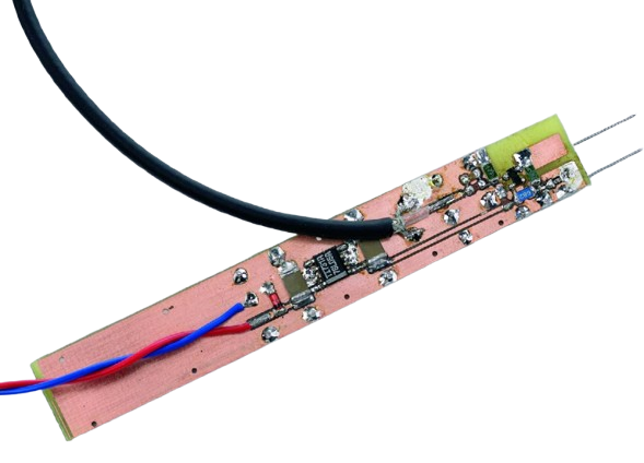
The board was designed to fit in a metal tube.
Active Probe Circuit
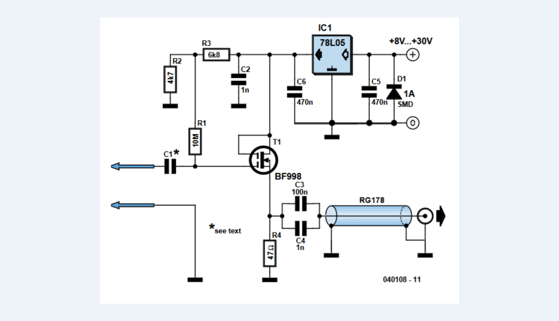
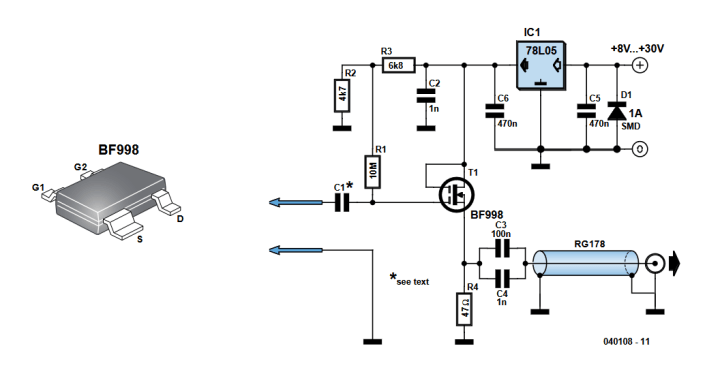
The active probe circuit is fairly simple. Refer to the circuit diagram of the do-it-yourself active probe. A dual-gate MOSFET guarantees light, uniform loading of RF signals over a frequency range extending well beyond the 1-GHz mark.
Circuit diagram of the active probe.
"A dual gate MOSFET, T1, is used in a source-follower configuration," the designer explains. "This provides a low output impedance to drive the coax cable and test equipment. The signal at the probe tip is applied to gate 1. The impedance at gate 1 is a very high resistance shunted by a few picofarads of capacitance. The choice of MOSFET used in the circuit is not critical ... Be sure however to steer clear of ‘-R’ suffix devices because they have a different pinout and will not work on the proposed PCB."
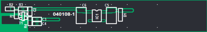
The PCB was designed with compactness and low input capacitance in mind. Hence, the use of SMD parts.
The PCB was designed with compactness and low input capacitance in mind. SMD parts were used.
The Original Project
The article, “Poor Man’s 1-GHz Active Probe,” appeared in Elektor April 2004. You can download the article for free during the two weeks following the publication of this news item. Enjoy the article!
Editor's Note: The article was first published in a 2004 edition of ElektorMag. Some of the components, products, PCBs, and/or links may no longer be available. Still, we feel the educational content is valuable, and we think it will inspire you to start new projects of your own.
Subscribe
Tag alert: Subscribe to the tag Circuits & Circuit Design and you will receive an e-mail as soon as a new item about it is published on our website!
Elektor Magazine has been one of the leading sources of information on electronics for engineers, designers, start-ups and companies for 65 years. Our magazine is powered by an active community of electronics engineers – from students to professionals – who are passionate about designing and sharing innovative ideas.
For them, we publish hundreds of items a year, in formats such as articles, videos, webinars, and other learning formats. Our mission is to share knowledge in every possible way and inspire readers with the latest developments within the electrical engineering sector.
Thank you for your vote!
Leave further comments in the fields below.
Thank you for your vote!
If you wish to leave a comment with your rating, please first use the login below. If not, just close this window.


Discussion (0 comments)