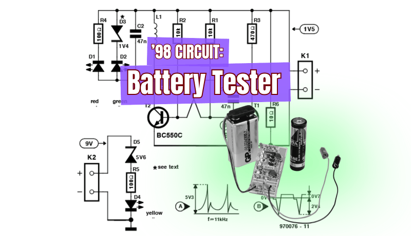
A blast from the Elektor archives: this clever 1998 battery tester uses a simple LED display to reveal a battery’s true condition under load — even below 1 V. Built from standard components and no fragile meters, it’s a timeless design that still inspires practical, low-cost testing today.
Elektor presented W. Zeille's battery tester project in July/August 1998. The design does exactly what it is supposed to do: it checks the true condition of a battery under load. The circuit uses only standard components, keeping costs low and construction straightforward. Instead of a delicate moving-coil meter, the battery voltage is indicated by a rugged solid-state LED display. A special feature of the design allows even voltages below 1 volt to light an LED, making the tester suitable for checking almost any small battery.
The Circuit
In the original article about the design, Elektor and Zeille noted that, even though the battery tester’s circuit diagram was simple, it could have been even simpler had they used the traditional moving-coil meter for the read-out. Because of the vulnerability and cost of such a mechanical meter, the team decided to replace it with a totally electronic alternative: an array of LEDs with different colors. However, to make an LED light, they needed a voltage between 1.6 V and 2.4 V. That was a bit of a problem, obviously, if you were using a 1.5-V battery as the power source!
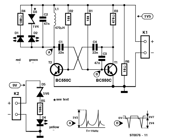
The battery tester is simple. Any 1.5-V dry cell may be connected to K1,
while K2 is used for PP3 style 9-V batteries.
“The problem was solved by calling in the help of an astable multivibrator (AMV),” the Elektor and Zeille noted. “Here, the AMV is built around T1 and T2, and converts the 1.5-V battery voltage connected to K1 into an alternating voltage with a level of more than 5 Vpp which is developed across choke L1. The output frequency of the AMV is about 11 kHz.”
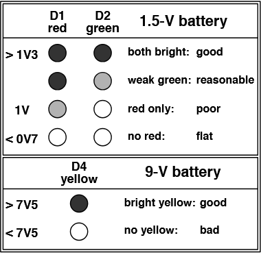
Two LEDs are connected in parallel with L1. Series resistor R4 belongs with the red LED, D1. Its value is such that the LED lights when the input voltage is just over 1 V. The green LED, D2, has a Zener diode instead of a resistor. The diode enables the LED to light at a battery voltage of 1.3 V or higher.
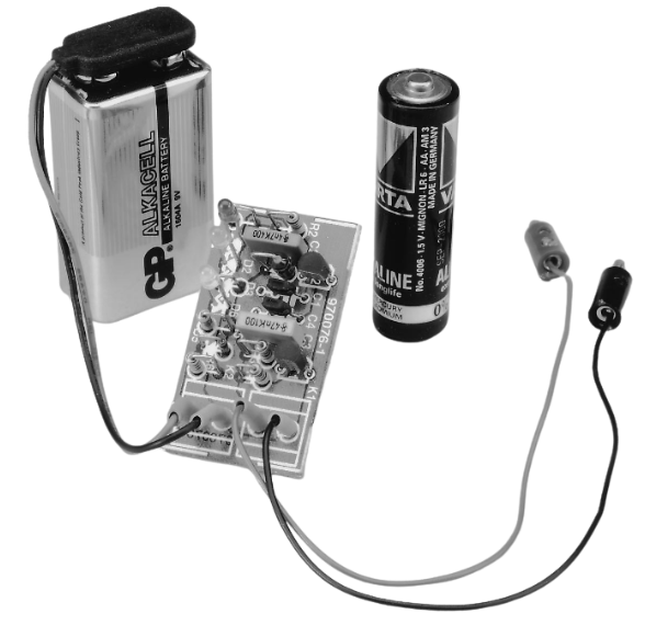
The project used short, flexible wires.
“Although the tester draws a current of about 30 mA, it is a too light load for battery test purposes,” Elektor and Zeille noted. “That’s why resistor R6 is connected in parallel with the battery terminals. The value of 10 Ω indicated in the circuit diagram should be looked upon as a useful average for the most commonly used battery types. If you only test ‘lady’ or ‘pen-light’ cells, then the load current may be made a little smaller, and R6 may be increased somewhat to, say, 15 Ω. For ‘baby’ and ‘mono’ cells, on the other hand, it may be better to adopt a slightly higher load current, and you may consider dropping the value of R6 to 6.8 Ω or so. Purists may, of course, fit a load switch to select between the two resistor values.”
Readout
Using the Battery Tester
Two short, flexible wires were used to connect the 1.5-V battery being examined to connector K1 on the board. Elektor warned: “Watch the polarity!” LEDs D1 and D2 then indicated the state of the battery. A battery was only deemed “good” if the green LED illuminated at a reasonable intensity.
To make the tester as versatile as possible, a test option for 9-V (PP3) batteries was added. These batteries could be connected to K2, and the test circuit consisted of no more than a yellow LED (D4) with a Zener diode (D5) and a resistor (R5) in series. The relevant component values enabled the LED to illuminate if the battery voltage was greater than 7.5 V.
The Battery Tester Project
The original article, “Battery Tester for all 1.5V and 9V Batteries,” appeared in Elektor July/August 1998. You can read the article for free during the two-week period following the publication of this post. Enjoy!
Editor's Note: This article first appeared in a 1998 edition of Elektor. Given the project’s age, the components might not be available. Nevertheless, we think the design will inspire you to start a project of your own.
Subscribe
Tag alert: Subscribe to the tag Circuits & Circuit Design and you will receive an e-mail as soon as a new item about it is published on our website!
Elektor Magazine has been one of the leading sources of information on electronics for engineers, designers, start-ups and companies for 65 years. Our magazine is powered by an active community of electronics engineers – from students to professionals – who are passionate about designing and sharing innovative ideas.
For them, we publish hundreds of items a year, in formats such as articles, videos, webinars, and other learning formats. Our mission is to share knowledge in every possible way and inspire readers with the latest developments within the electrical engineering sector.
Thank you for your vote!
Leave further comments in the fields below.
Thank you for your vote!
If you wish to leave a comment with your rating, please first use the login below. If not, just close this window.


Discussion (0 comments)