Whether you are designing, repairing, or testing audio and hi-fi gear, a reliable frequency counter is a must-have tool. This classic frequency counter was a great DIY solution for audio work.
Whether you are designing, repairing, or testing audio and hi-fi gear, a reliable frequency counter is a must-have tool. This classic frequency counter was a great DIY solution for audio work, offering three switchable measuring ranges — up to 100 kHz — and a four-digit display tailored for the frequencies that matter most. It was designed to be integrated into a function generator or to be made into a standalone unit with just a few added components.
Counter Circuit
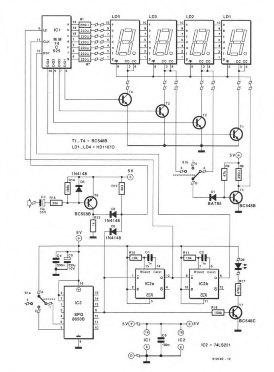
Designed by F. Hueber and presented in the January 1992 edition of ElektorMag, the heart of the circuit is IC1, a TTL-compatible 74C925 CMOS IC. "Housed in a 16-pin DIL package, this device contains four decade counters, a status memory, a multiplexer, and a seven-segment decoder for a four-digit display. The common-cathode, seven-segment display, LD1-LD4, is driven by transistors T1-T4. The segments of the four digits are fed in parallel via limiting resistors R1-R7."
The counter circuit. Click for PDF.
Transistor T5 controls the decimal point so that it activates in sync with the selected metering range. It is cut off by the display drivers via D1 when S1b is in position: the decimal point then illuminates. To ensure the transistor switches off promptly, it must be a germanium or Schottky type, as the base-emitter potential of a standard silicon diode remains too high. To prevent any problems with the calibration of the timebase, the designer decided to clock it with a Seiko-Epson SPG8650B (IC3).
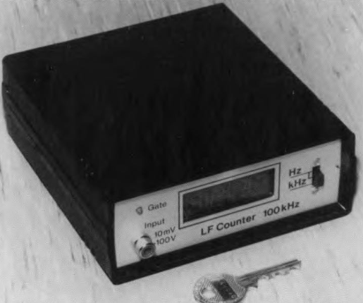
The LF Counter
Since it is a modular design, the counter can be housed in a variety of instrument cases. The prototype's case measured 60 × 150 × 132 mm (H × W × D). The counter and display boards are fitted to the front panel; the preamp and power supply boards are fixed to the bottom panel.
Calibration
Curious about calibration? Hueber explained:
“Connect an oscilloscope to the output of the Schmitt trigger and inject a 10 mV sinusoidal signal of about 20 kHz into the Input socket. Adjust P1 until the waveform on the oscilloscope is a true square wave. If no oscilloscope is available, adjust P1 so that the counter reading remains the same for sinusoidal and rectangular signal inputs (at a level of 10 mV). The counter has no overflow indication, so that, if, for instance, the 10 kHz range is selected, and the input signal has a frequency of 10.234 kHz, it is displayed as 0.234 kHz. It is, therefore, advisable when an unknown frequency is being measured to select the highest range first and then go down as required.”
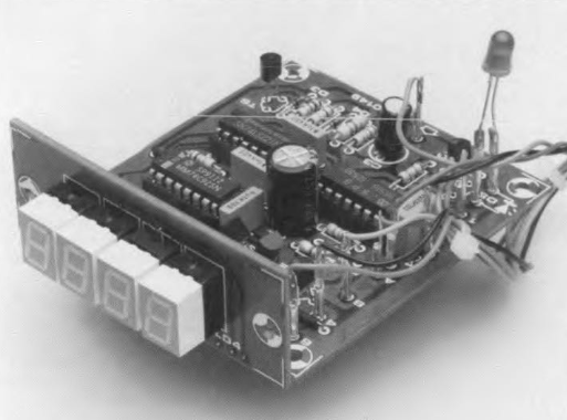
The display and counter boards must be fitted together at right angles.
Low-Frequency Counter Project
The article, “Low-Frequency Counter,” appeared in Elektor January 1992. The article is free to download during the two weeks following the publication of this post. If you begin a project of your own, share your progress on the Elektor Labs platform!
Editor's Note: This article was first published in a 1992 edition of ElektorMag. Due to the project’s age, some components, PCBs, products, or links might not be available. With that said, we think you’ll find the project interesting, and we believe it will inspire you to start new DIY electronics projects at your workbench.
Subscribe
Tag alert: Subscribe to the tag Circuits & Circuit Design and you will receive an e-mail as soon as a new item about it is published on our website!
Elektor Magazine has been one of the leading sources of information on electronics for engineers, designers, start-ups and companies for 65 years. Our magazine is powered by an active community of electronics engineers – from students to professionals – who are passionate about designing and sharing innovative ideas.
For them, we publish hundreds of items a year, in formats such as articles, videos, webinars, and other learning formats. Our mission is to share knowledge in every possible way and inspire readers with the latest developments within the electrical engineering sector.
Thank you for your vote!
Leave further comments in the fields below.
Thank you for your vote!
If you wish to leave a comment with your rating, please first use the login below. If not, just close this window.


Discussion (2 comments)