Back in 1977, for most people, if you weren’t home to hear a ringing phone, the moment was gone forever. Unless, that is, you built Elektor’s ingenious "Telephone Tell-Tale" missed-call indicator. Check out the circuit!
When you step away from your phone today, you take it for granted that you’ll know if someone tried to reach you. Your phone logs missed calls and unread messages. But back in 1977, for most people, if you weren’t home to hear the ringing, the moment was gone forever. Unless, that is, you built Elektor’s ingenious “Telephone Tell-Tale” missed-call indicator.
A Missed-Call Indicator, Before It Was Cool
Published in the July/August 1977 edition of Elektor, the Telephone Tell-Tale was an early “missed call” notification system for phones. At the time, answering machines were pricey tape-based devices, and telephone companies didn’t offer missed call services for residential lines.
The Tell-Tale project solved that problem with a simple but brilliant approach: an LED illuminated when the phone rang at least eight times. It stayed lit until someone manually pressed a reset button.
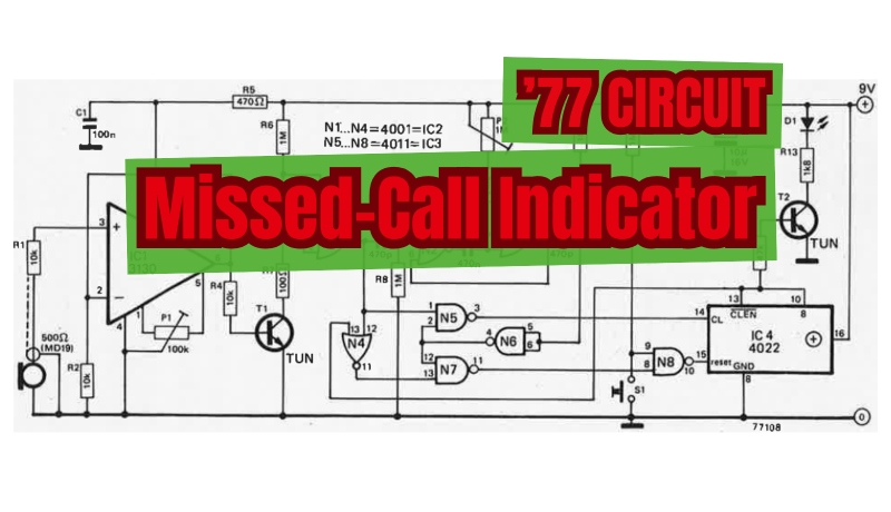
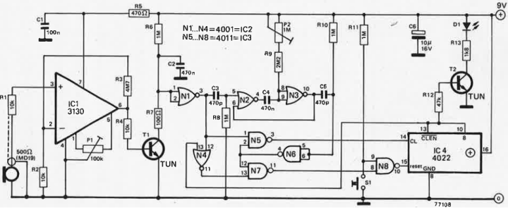
Missed-call indicator circuit.
The Missed-Call Indicator Circuit
A microphone capsule mounted beneath the phone detects the ringing sound and sends it to IC1 for amplification. When no ring is present, capacitor C2 stays charged. As soon as a ring occurs, transistor T1 conducts, discharging C2. This causes the output of N1 to go high, triggering the monostable multivibrator (MMV) formed by N2 and N3, which remains active for a period set by potentiometer P2. When the MMV times out, it sends a pulse via N6 to N5 and N7. If a ring is still being detected (N1’s output high), the pulse passes through N5 to the clock input of counter IC4.
Elektor explained:
“Since the duration of the signal is normally around 1 second, P2 should be adjusted so that the MMV remains triggered for just under a second. This ensures that only signals of approx. I second or longer will be recognized by the circuit and clock the counter. If a signal lasts for less than the preset time, the output of N1 will be low and the pulse from N6 will be passed through N7 and N8 to reset the counter. In order to further decrease the sensitivity of the circuit to spurious signals, the last output of the counter is taken to drive the LED, so that the phone must ring at least 8 times without interruption before the LED will light up. This number can naturally be reduced by using one of the other outputs.”
Running from a 9-V battery at only 5 mA, the design provided a simple, low-power, and entirely acoustic missed-call memory. Everything was accomplished without making any electrical connection to the phone line.
The Original Project
The original article, “Telephone ‘Tell-Tale,’” appeared in Elektor July/August 1977. You can read the article for free during the two-week period following the publication of this post. If you develop your own circuit, please share your progress on the Elektor Labs platform!
Editor's Note: This article first appeared in a 1977 edition of Elektor. Given the project’s age, some components or products might not available, and some design techniques might seem antiquated. However, we believe the design will inspire you to start new DIY electronics projects of your own.
Subscribe
Tag alert: Subscribe to the tag Circuits & Circuit Design and you will receive an e-mail as soon as a new item about it is published on our website!
Elektor Magazine has been one of the leading sources of information on electronics for engineers, designers, start-ups and companies for 65 years. Our magazine is powered by an active community of electronics engineers – from students to professionals – who are passionate about designing and sharing innovative ideas.
For them, we publish hundreds of items a year, in formats such as articles, videos, webinars, and other learning formats. Our mission is to share knowledge in every possible way and inspire readers with the latest developments within the electrical engineering sector.
Thank you for your vote!
Leave further comments in the fields below.
Thank you for your vote!
If you wish to leave a comment with your rating, please first use the login below. If not, just close this window.


Discussion (0 comments)