Circuit: Simple Transistor Tester with LED or Piezo Buzzer indicator
A transistor tester can be a handy addition to your electronics workbench. This versatile transistor tester design, first presented a decade ago, enables you to quickly assess the functionality of NPN/PNP transistors, JFETs, or (V)MOSFETs, and helps you accurately identify their leads.
A transistor tester can be a handy addition to your electronics workbench. This versatile transistor tester design, first presented a decade ago, enables you to quickly assess the functionality of NPN/PNP transistors, JFETs, or (V)MOSFETs, and helps you accurately identify their leads.
Transistor Tester Design
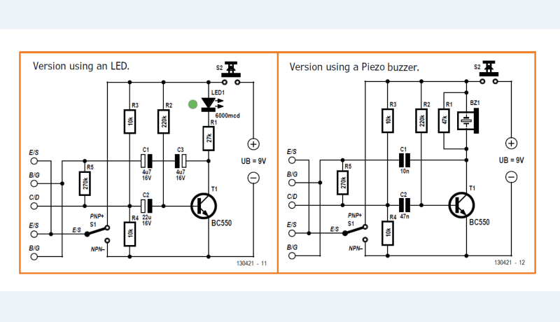
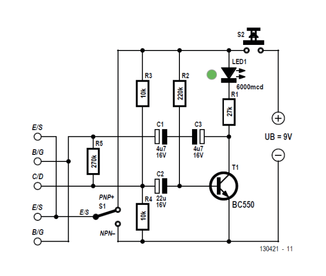
A three-legged transistor or FET can be connected in six possible configurations, but only one is correct. This compact circuit offers a straightforward and reliable way to identify the correct configuration while simultaneously performing a functional test of the device. The tester circuit itself includes a transistor that, when paired with the transistor under test (TUT), forms a multivibrator circuit. The tester features five closely positioned sockets, each clearly labeled for easy identification:
E/S – B/G – C/D – E/S – B/G
This enables testing using the following configurations:
According to Hans-Norbert Gerbig, “the multivibrator oscillates and flashes the high-efficiency LED when the test transistor is correctly connected.” Refer to the circuit using an LED.
Subscribe
Tag alert: Subscribe to the tag Circuits & Circuit Design and you will receive an e-mail as soon as a new item about it is published on our website!
“The LED may also flash when the E and C leads are switched, but the flash rate will be faster,” Gerbig explained. “This reflects the fact that some types of transistor will operate with their emitter and collector leads switched although their performance characteristics will not be the same as a correctly configured device.”
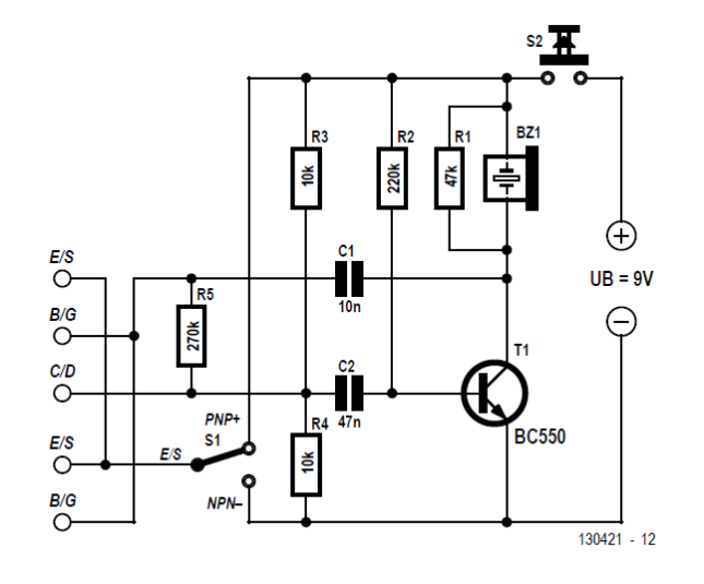
Version 2 of the tester features a piezo buzzer in place of the LED indicator. The value of the frequency determining capacitor has been reduced compared to its value in the other version so that the oscillation frequency is audible.
Version using a Piezo buzzer.
“A low buzz indicates that the transistor is correctly configured and working, no sound indicates the test transistor is either wrongly configured or dead.”
Simple Tester Article
Gerbig’s article, “Simple Transistor Tester,” was published in Elektor July/August 2014. We’ve made the article freely available to everyone in the community. Enjoy!
Editor's Note: This article was originally published in a previous edition of our magazine. Please note that some of the products (e.g., PCBs) and links may no longer be available. However, we believe the educational content remains valuable and hope it inspires you to embark on new and exciting projects.
Subscribe
Tag alert: Subscribe to the tag Test & Measurement and you will receive an e-mail as soon as a new item about it is published on our website!
Elektor Magazine has been one of the leading sources of information on electronics for engineers, designers, start-ups and companies for 65 years. Our magazine is powered by an active community of electronics engineers – from students to professionals – who are passionate about designing and sharing innovative ideas.
For them, we publish hundreds of items a year, in formats such as articles, videos, webinars, and other learning formats. Our mission is to share knowledge in every possible way and inspire readers with the latest developments within the electrical engineering sector.
Thank you for your vote!
Leave further comments in the fields below.
Thank you for your vote!
If you wish to leave a comment with your rating, please first use the login below. If not, just close this window.


Discussion (0 comments)