
Circuit: The Multitester
on
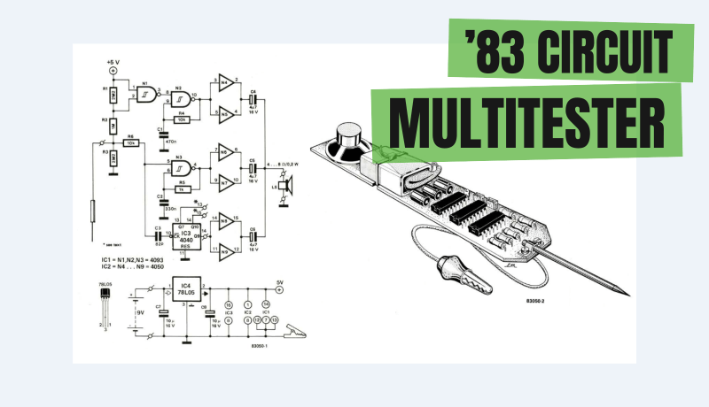
Test equipment can consume valuable workshop space, particularly in smaller areas. E. Osterwick’s compact “Multitester” design from 1983 addresses the issue by integrating multiple simple testcircuits - a logic probe, clock pulse detector, and voltage level detector — into one compact unit. Without visual displays, it uses audio feedback through a small speaker for output indication.
The Multitester-project
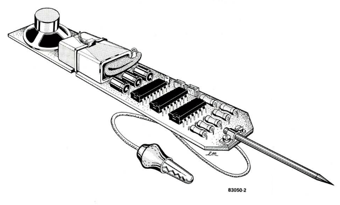
The Multitester circuit consists of three ICs and a small loudspeaker. Its simplicity however does not prevent it from being able to check for four different parameters at any point in a circuit under test.
1. A voltage level below 0.8 V, interpreted as a logic 0.
2. A voltage level between 1.8 V and 5 V, indicated as a logic 1.
3. A test point that has an undefined level (a tristate output) or is open circuit.
4. The existence of a clock signal or pulse train.
Each condition is indicated by a different acoustic signal.
The Circuit
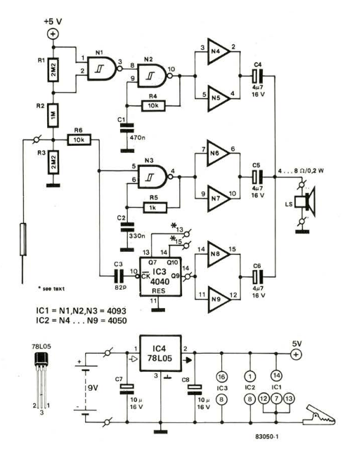
Refer to the circuit diagram. Figure 1. As you can see, the Multitester contains very few components besides the three ICs. The basis of the circuit consists of two oscillators, N2 and N3, and the counter IC3.
"Two oscillators, gates N2 and N3, and the counter IC3 form the basis of the circuit," Osterwick wrote. "The detector probe is connected to the junction of R2 and R3. If the probe touches a point in the circuit under test that is at 0 V resistor R3 will be short circuited. This will cause the voltage level at the junction of resistors R1 and R2 to fall. The output of gate N1 will rise to logic '1' to activate the oscillator formed by gate N2. If the probe is taken to +5 V the oscillator formed by N3 will be switched on.”
The Original Project
The article, “Multitester” appeared in Elektor June 1983. You can access the article for free during the two weeks following the publication of this news item. If you start a project, please consider sharing your progress on the Elektor Labs platform!
Editor's Note: This article originally appeared in a 1983 edition of ElektorMag. Given the project’s age, some components, products, or links may no longer be available. However, we believe the content will inspire you to start new electronics projects at your workbench.


Discussion (0 comments)