
Efficient Solenoid Valve (130258-I)
We have in our house a reverse osmosis water filter for filtering the tap-water up to drinking water quality. The filter fills a little reservoir of 25 liters. We used to manually turn on and off the tap of the filter, but of course, as it takes 4 hours to fill the reservoir, we usually forgot to close the tap, spilling lots of water.
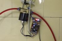
We have in our house a reverse osmosis water filter for filtering the tap-water up to drinking water quality. The filter fills a little reservoir of 25 liters. We used to manually turn on and off the tap of the filter, but of course, as it takes 4 hours to fill the reservoir, we usually forgot to close the tap, spilling lots of water. So I ordered a 12VDC valve on ebay (12 euro, suitable for pneumatics and hydrolics) in order to automate the process. The valve stays open untill a float switch indicates the reservoir is full. Normally, the 8 ohm coil of the valve consumes about 18W. Quite a lot, also not nice for the door-bell transformer from where I wanted to derive the power. I remembered a 2004 article from Elektor to reduce power consumption in relays, which is based on the fact that relays actually only need a fraction of the power to keep in position after the initial switching on. I first made simular circuitry like that, but I was not happy with the idea that the vast majorty of power was dissipated by the power transistor (I had to attach the power transistor to the valve itself to let it be cooled by the flowing water). So I looked to a switching transistor method. Also, the circuitry needed to be less sensitive to small fluctuations of the water level. Small ripples causing the valve switching on and off. I figured out that the best thing would be that the valve would react with a delay of a minute or so for both switching on and off. So I decided to make a small microcontroller circuit for accomplishing these two things. All components I took, were ones I had already at home (others components may be more suitable). The microcontroller is the PIC12F683. Three leds give some information about the state: the white led indicates the circuit is receiving power (I was mistaken here, see update 4). The blue led indicates the valve is open and the red led indicates the 'delay state': in this case the floating switch has changed state, but the valve hasn't yet. The leds also are driven by PWM in order to save power consumption. The circuit greatly economises the power: with the valve I used, total power of only 0.4W is more than sufficient for reliable working instead of the normal 18W. It has been working to our satisfaction since December. Circuit diagram and program (in assembler) will follow soon.
Update 1: the circuit and program are uploaded. As you can see I did not make a pcb as it was meant as a single copy, small home-project. The button in the scheme is used to change the state from on to off to automatic. Currently, in the program as it is now, the state is saved in the EEPROM, so on power on returning to the same state. The EEPROM is also used for logging some data, like, counting of power-ons, counting switchings of the valve, hours of power-on, hours of the valve been switched on. But these functionalities have not been tested and I think to just to let all features which involve the EEPROM out in the final version. So in that case a PIC12F without EEPROM can used. The unit will then power on in automatic mode by default. As I wrote, I just used the components which I had at hand at home. So the big flyback diode and mosfet can also be seen as overkill.
There are two minor points: 1.) the valve quickly switches on and off upon power on, because the PIC12F powers up more slowly than the 12V. (5V directly from the PIC12F output was not enough to drive the gate of the mosfet). and 2.)When switching on the fluorescent lights in our cellar, where our filter is located, the circuit resets. The loads seem to create a serious dip. Bypassing the circuit with a 2200µF capacitor did not help. (Maybe disabling or modifying Brown-out reset of the PIC12F. I did not have a look into this yet.)
Both these minor points are however not that important in this application for normal functioning.
At the beginning of the program there are some constants which can be set. A little attached diagram showing the signals helps to clarify the meaning of most of the constants.
As you can see in the diagram, the voltage of the valve drops back slowly, this to reduce the flyback current.
The duty cycle for each led apart can be set in the constants, expressed as 1/10x, so a value of 5 means a duty cycle of 1/50. (The current of the leds is limited by the resistors to approx. 100mA each.) At the moment both the duty-cycle of the blue and the red LED are set to 1/50 and the duty cycle of the white LED to 1/150.
Update 2 A pull-up resistor (R11) is added to the schematic. Pin GP3 has no internal pull-up.
Update 3 The transistors I used were actually BC548's instead of BC547's; I updated the schematic.
When the MOSFET is replaced with a type that only needs 5V to open, then transistor Q5 and the 12V supply can be removed. Some other solution can be used then for a 5V supply for the microcontroller. Then, the signal to the MOSFET needs to be inversed in the software. Doing so, it will also prevent the valve to open and close quickly upon power on. (I used the IRF530, because I had no other MOSFETs at hand.)
Update 4: the white LED is actually indicating that the circuit is in automatic mode (and not that the circuit is receiving power, as I wrote earlier). The red LED indicates the wait-states, so will only light up temporally during the automatic mode. During off - mode, no LEDs light up.
Update 5 (aug 25 2013): IRL540 seems to be an easy to get, often used replacement for the n-channel mosfet that can be driven directly by the pic (see update 3).
I'm thinking now of a more cost effective circuit with a PIC10F200, more about this later. (Maybe I should start another project?)
Update 6 (sept 10 2013): I've added an alternative software try-out for the PIC10f200. Yet it has to be tested. Also added software with pic10f200 and 2 valves in order to make them using less power. But no water level logic, only digital inputs, one for each valve. Also not tested yet. The frequency has lowered to 244Hz from 488Hz in these alternatives, this might be too low.
Update 7 (sept 21): new schema version added. I've ordered some other valves to test as well. The software can still be simplified and enhanced, so that a frequency of 488Hz or higher is possible with pic10f200 or pic10f202. Preferably the flyback diode is a Schottky type. It is not only to protect the transistor from over-voltage, but it keeps also the current going through the coil in the death part of the duty cycle. The diode's current-capacity, I think, should be rated Ucoil / Rcoil.
Update 8 (march 2014) I'm glad it got published, however I'm sorry I didn't find time to work on a simplified version wtih the pic10f with better code practice. However, if someone feels like to work on this, I posted the (untested) draft for this.
Want to build a project?
Bring your design to life with the Elektor PCB Service, powered by Eurocircuits. Upload the project files and order professionally manufactured PCBs or assembled boards through a proven European production platform.
Supporting KiCad, Eagle, Gerber, and ODB++ formats, the service is suitable for everything from prototypes and validation builds to series production and volume manufacturing.
Made in Europe. Fast. Reliable. Professional.
Discussion (4 comments)