
Error Analysis: Engineering Insights from Pros and Makers
May 11, 2021
on
on
You can learn a lot from your engineering mistakes and from the mistakes of other engineers and makers. In this Error Analysis collection, several community members offer helpful electronics-related insights and engineering tips.
Revealing Semiconductor Behavior
As a chemical engineering student, I was testing the formation of tin oxide substrates on glass as a basis for cadmium-based solar cells. This involved doping, floating glass on a molten lead bed and spraying cadmium chloride in the air. Weeks of experiments didn't yield any usable results. Frustration. The success of the prototype was tested by measuring the current in forward and reverse potential (i.e., diode behavior). At some stage, I started to mistrust the state-of-the-art electronic multimeter and used my own analog multimeter. Suddenly, there was semiconductor behavior measurable. What I learned was that the analog meter using higher measurement voltages revealed the behavior of semiconductors and band gap width. This was 40 years ago now, and it still serves as a lesson. Sometimes you just need to kick harder to reveal difference in behavior. — Diederik Weve, Hardware Engineer, The Netherlands)Try Error Avoidance
More of an error avoidance action. I designed and built a relay-based 30 pad Rocket launch controller with another individual doing spin-offs of the design. Since the relays are 12 V automotive relays and our power source is 12-V jumper batteries, we included a power diode in series with the battery connection positive bus. Youth and inexperienced adults might have been involved with setting up the system, and since the continuity check of the igniter was two LEDs in series, we did not want to have a reversed polarity destroy them. We could afford the 0.7-V drop of the power diode and have had successful deployment of these controllers for over 17 years. Several of the smaller controllers have made the trip to the National TARC contest from three to five times. The protection works. I first saw this being done in car radios in the 1980s. The article suggestion of using power Schottky diodes for the lower voltage drop is a great idea I had not considered. — George W. Shaiffer (Retired Electronics Technology Instructor, United States)Prep for Errors
While attempting to repair a Bluetooth speaker I connected the battery terminals the wrong way round and watched the ensuing smoke and associated smell. I realized shortly afterwards what I did wrong! In the future, I will create a test lead with a fast-acting fuse inline so that if battery terminals are connected incorrectly, hopefully, the fuse will blow first. — Mayank Joshi (Hardware Engineer, United Kingdom)Design, Test, and Alter
We were designing a new SCR DC motor controller for a hydraulic pump motor (80 V, 1000 A) using our standard opto-isolated drive circuit for the three SCRs. This was to be a potted design for industrial use. Initial proving tests were no problem, allowing 1200+ A to be commutated. However, when potted, the circuit would only commutate 800 A. De-potted and it worked again. The problem was the permittivity of the potting compound increasing the capacitance to the gate on the opto SCR IC. The standard values for the C-R on the gate snubber needed to be altered to cater for this. In the end, a very successful product. — Ed Dinning (Retired Power Electronics Engineer, United Kingdom)When Grounding is Dangerous
Hello. A very good opportunity for me to share my experience. A few years ago, on a DC-to-AC converter, I replaced all the IGBT power modules by new compatible parts. Per module, there are two IGBTs: one acts as transistor and from the other only the reverse diode is used as a freewheeling diode. This diode is in parallel with the IGBT transistor. So, as the transistor was not used, I had to block it. And so I connected the gate to the ground believing that this would work. It didn't. The correct solution was to connect the gate to the emitter. I will never make this mistake again! Another mistake: I forgot that scope alligator clips are connected to earth. This is a basic scope property overlooked by many beginners. Best regards! — Stephane (Hardware Engineer, France)Check Your PCBs
When building a circuit, I blindly trusted the assembly print on the board. During the first start-up, an electrolytic capacitor burst. A check showed that the polarity of the electrolytic capacitor was wrong on the printed circuit board. — Rolf Zeller (Academic/Teacher, Germany)Take a Step Back
Two particularly shameful mistakes over 25 years of industrial, automotive, military, space design: inverting a diode between the symbol and the footprint and using an 80-pin footprint for a 144-pin microcontroller... a waste of time and significant money to redesign library and PCB, and the loss of a customer! (The diode caused a board to explode in the presence of the customer). Something to kepe in mind: check things in two different ways! Footprint to symbol and symbol to footprint. And, if possible, get a peer review. Being too focused on one thing makes us forget about other things! — Yann Leidwanger (Hardware Engineer, France)Look for the Unexpected
When I started at college, I built a DVM and spent many hours building it and quite some time calibrating it. I calibrated the DC part with no problem. When it came to AC calibration, it kept dying. Only after the second time I realized what had happened. I was using a variac to reduce the mains to a level suitable for the meter. Only I would turn off the mains to the variac before removing the meter forgetting that the back EMF from the variac would take out the FET in the meter. I always look for the unexpected when working with hardware, but in this case, it would have been expected if I had thought of it. — David Twist (Hardware Engineer, UK)Be Careful When Being Careful
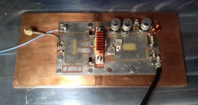
I designed a circuit for a 144-MHz power amplifier with a BLF188XR transistor. I wanted to start carefully and therefore limited the input power. At first power-on everything was OK. But when applying a signal to the input of the circuit, I found that the transistor heated enormously even though I was only at 1/3 of the maximum power of 1 KW. I searched for a long time and smoked a transistor until I read the datasheet in detail and discovered that the performance of this type of transistor depends on the supply voltage and the applied power. For 1 KW at 50 V it has an efficiency of more than 80% but for 300 W at 50 V it is only 20%. I finally understood that this lack of efficiency was dissipated as heat by the transistor... With full power or reduced supply voltage if you are below the required power, it works very well. — Arnaud (IT Technician and Ham Radio Enthusiast, France)Even Great Components Can Fail
When I was studying for engineering way back in the day, I was fascinated with the 7805 voltage regulator when it was introduced. During that time, we used to have a series-pass-transistor-based voltage regulator circuit with a Zener diode as reference voltage. So, when the three-pin regulator came to market, it was really exciting (as well as very expensive in relative sense). When I read the application note, it was mentioned that the IC had all kinds of protection, such as over-current, over-temperature, short circuit, etc. So, I "saved" money to buy this wonderful chip. It was a prized possession at that time. I was excited. In one of the app notes there was a circuit showing how it can be used as a constant current source. I went to our college, met a professor, and told him that I wanted to try this exciting circuit. I went to the lab and set it up, and all was going well ... Alas, black smoke appeared. I was shocked that the "miracle chip which has all protections " failed. I could not believe my eyes. — Narayanan Nampoothiri (Hardware Engineer, India)Check All Component Values
I wanted to repair two mains sockets controlled by a remote control. The receiver had a special integrated circuit for pulse decoding. After identifying the deceased ICs, I ordered them online in Asia because they are impossible to find in Europe as they are obsolete. After receiving the devices, I replaced the first and everything worked. Great! So I replaced the second too but it did not work. I searched for days to see if there were maybe other broken parts until I discovered that the new IC I had installed was only half functioning. One of the two chips received was a fake! Today, I only order semiconductors in Europe. It lowers the risk of fakes. If you want to order passive components at discount prices, my advice is to check their values as soon as you receive them, so you can be sure you can solder them without risk. — Thierry Chabert (Hardware Engineer, France)Submit Your Error Analysis
Would you like share details about an engineering error? Perhaps learned an important lesson from the experience? Your story just might help thousands of other engineers and electronics enthusiasts! Submit an Error Analysis post todayRead full article
Hide full article
Discussion (0 comments)