
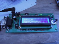
Hamster Run-O-Meter
Did you ever wonder how fast your hamster can run? With this project, you may find out!
If there is a treadmill in its cage, with the circuit we present here you can not only measure a hamster's top speed, but also the total distance your hamster travels between the beginning and end of a measurement. Of course the duration of the measurement is also recorded and from these data you can calculate the average velocity.
The idea was not to mess (too much) with the cage or hamster wheel, for that reason two IR reflection sensors and a small strip of reflecting material (tin foil) stuck to the wheel are used to register rotations. In the first setup only one sensor was used, but the second one was added to eliminate measurement errors if the hamster is just rocking the mill. Two sensors register complete turns of the mill.
Up to 15 measurements can be stored in the internal EEPROM of the microcontroller, each measurement contains time period, total distance and top speed.
Hardware
The hamster run-o-meter is controlled by IC2, a PIC18F26K22 microcontroller. K3 is pin compatible with a Microchip Pickit programming interface and can be used to flash the microcontroller. Push button S1 resets IC2.
A standard 2 x 16 character LCD is used for displaying settings and data. P2 controls the contrast of the display and the backlight can be switched on and off by the microcontroller via transistor T2.
ENC1 is a rotary encoder with integrated push button for changing display and settings.
For the prototype in the Elektor Lab we implemented two TCRT5000 IR reflection sensors to register the turning of the wheel, but nearly any other combination of IR LED and detector will do. The output of the PIC is a 38kHz modulated square wave, so a TSOP4838 remote control sensor (or any other 38kHz type) in combination with an IR LED (e.g. CQY99) will do the trick too. The latter solution is a bit more bulky and more difficult as far as mechanical construction is concerned, but this modulation makes the sensors less sensitive to other (IR) light sources. Also, the opamp and Schmitt-trigger gates are not absolutely necessary when you use a remote control sensor, but they won’t harm either.
The LEDs are connected in parallel between pin 4 and 5 of K2 (VCC to anodes and control voltage to cathodes respectively), P1 can be adjusted to control the intensity of the LEDs.
The emitters of the TCRT5000s are connected to GND (K2 pin 3), the collector of one sensor is connected to pin 1 ok K2, the other to pin 2. IC3 and IC4 clean up and filter the output signals of the detectors.
LED3 blinks on power up and toggles on/off after every turn of the wheel during measurements.
The PCB also has two LEDs (LED1 and LED2) that indicate the status of the sensors. They light up when there receiving reflecting light. This indication runs parallel to the option “Sensor status” on the LCD (more about that later) but the LEDs react faster than the relatively slow LCD display.
Software
The menu structure of our hamster Run-O-Meter is presented in Figure 2. The meter is operated by a combination of rotating (red lines) and pressing (blue lines) the optical encoder. The green line is an automatic (delayed) transitions.
At power on the LCD shows “Hamster Run-O-Meter”, pressing the encoder’s button presents the first menu item: “Start measuring”. You can either start a measurement by pressing the button again or rotate the encoder to cycle through the other main menu items.
In the “Controls” menu are two settings and one test item.
The diameter of the hamster wheel can be set between 12 and 35 cm. Once the correct number is selected, the button is pressed and the diameter is stored in EEPROM.
The second setting is the selection “Measurement Backlight on/off”. Because hamsters usually prefer to run during the night it can be annoying if the backlight of the LCD is on. The backlight can switch off automatically when a measurement starts, and back on when it is stopped. By turning the knob you can select “on” or “off”, this setting is stored in EEPROM when the button is pressed.
Next the LCD shows "Sensor status", on the second line two times “on”/”off”.
If a sensor does not receive reflected light “off” is shown. If it does receive light (the strip on the wheel passes the sensor), it shows the text “on”. In this way, it can be determined by turning the wheel whether the sensor is doing its job properly.
Pressing the button when “Show results” is on the LCD enables you to view each of the 15 stored measurements:
- the number of the measurement “Mx” (x runs from 1 to 15)
- the duration of the measurement in hh:mm format (minimum 00:01 and maximum 23:59)
- the maximum speed in xx.xx km/h (speeds < 0.50 km/h are discarded)
- on the second line “Total xxxxxx m” which represents the total distance travelled in meters
Rotating the knob will cycle through the 15 measurements, pressing the button will return to the Measurements menu.
Pressing the button when “Erase results” is displayed will erase all 15 measurements.
The last option in the main menu is “Switch backlight”, which –as the name suggests- enables you to switch the backlight on and off.
Assembling the PCB
Since all parts are through-hole types, soldering is not too difficult. Start with soldering the resistors, then the IC sockets, capacitor etc. Insert the IC’s into the sockets. K3, the connector for the programming interface, is only needed when you don’t have a pre-programmed PIC or if you want to experiment with your own version of firmware. It may be more convenient to solder it to the bottom side of the PCB.
For the LCD, solder the 16-pin socket strip to component side of the PCB, the 16-pin header to the bottom side of the display. Mount the four 10mm standoffs to the PCB, carefully plug the display into the socket-strip and observe if the LCD is level with the standoffs (probably not), use the washers to make it level before you screw the LCD to the standoffs.
Mechanical Installation
Glue a small strip (large enough to mirror the beam of an IR LED to the detector) of aluminum foil or any other reflecting medium on the outside of the wheel, facing the outside of the hamster cage. The sensors are preferably placed at (about) 180 degrees, i.e. a half turn of the wheel.
There are two possible methods for mounting the sensors, depending on the type of sensors you want to use.
In method 1, each “sensor” consists of a IR LED (e.g. TSUS5400 or CQY99, preferably with reflector) and a TSOP4838 IR receiver mounted next to each other on a small piece of veroboard. Bend them slightly towards each other, so the detector can “see” the reflected IR beam of the transmitter. You’ll need some kind of mechanical construction outside the cage to mount these PCBs/sensors. Of course the IR beams must not be reflected by the bars of the cage.
Please note that a TSOP4838 is very sensitive to IR remote controls, so don’t start zapping during measurements.
Method 2 allows for a smaller setup which, with a little skill, can be attached to the bars of the hamster cage. In this case two TCRT5000 combination sensors are used. These
have the collector of a phototransistor as output and therefore on the PCB the OPAMPs (IC4) and Schmitt-trigger inverters (IC3) translate these outputs to clean digital signals.
The method used with the TCRT5000 is less reliable than the method used with the TSOP4838.
Both setups need some fine-tuning. Mechanically, by “playing” with the location and angle of
the sensors (especially the distance to the wheel) and electrically by varying the current through the LEDs with potentiometer P1.
R1 = 1.8 kΩ, carbon film, 5%, 0.25W, 250V
R2 = 3.3 kΩ, carbon film, 5%, 0.25W, 250V
R3,R4,R5,R6,R7,R10 = 4.7 kΩ, carbon film, 5%, 0.25W, 250V
R8,R9,R11 = 1 kΩ, carbon film, 5%, 0.25W, 250V
R12,R14 = 470 Ω, carbon film, 5%, 0.25W, 250V
R13 = 100 Ω, carbon film, 5%, 0.25W, 250V
P1 = 4.7 kΩ, trimmer, flat
P2 = 10 kΩ, trimmer, flat
Capacitor
C1 = 100 µF, 50 V, 3.5 mm pitch, 8x11 mm
C2,C3,C4,C5,C8,C9 = 100 nF, 50 V, X7R, 5.08 mm pitch
C6,C7 = 22 pF, 50 V, C0G/NP0, 2.5 mm pitch
Semiconductor
LED1,LED2 = LED, yellow, 3 mm
LED3 = LED, red, 3 mm
LED4,LED5* = IR LED TSUS5400 (NOT on PCB)
T1,T2 = BC547C, 45 V, 100 mA, 500 mW, hfe=400
IC1 = MC7805, 5 V, 1 A
IC2 = 8-bit microcontroller PIC18F26K22 EPS 180341-41
IC3 = hex Schmitt-trigger inverter 74HCT14
IC4 = TLC272CP, dual JFET opamp
IC5,IC6 * = TCRT5000 - Reflective Photo Interrupter (NOT on PCB)
IC5,IC6 * = TSOP4838 remote control receiver 38kHz (NOT on PCB)
Other
LCD1 = 2 x 16 character LCD with backlight 120061-74
LCD1' = Pin socket, breakable, 1 row, 16-way, vertical
LCD'' = Pin header, breakable, 1 row, 16-way, vertical
S1 = Switch, tactile, 24 V, 50 mA, 6x6 mm
ENC1 = EC12E2424407 - Incremental Rotary Encoder, Insulated Shaft, Push Switch, 12mm, Vertical, 24 Detents, 24 Pulses
X1 = Crystal 16 MHz, 18 pF
K1 = DC barrel jack, 1.95 mm pin, 12 V, 3 A
K2 = Sub-D, 9-way, female
K3 * = header male 6 pin, 0.1" pitch vertical
n/a = IC socket, DIP-28, narrow (IC2)
n/a = IC socket, DIP-14 (IC3)
n/a = IC socket, DIP-8 (IC4)
Miscellaneous
PCB 180431-1 V1.1
Threaded hex spacer M3 x 10mm
machine screw M3 x 5mm
spring washer M3
nut M3
9- way D Sub connector male, cable mount
* = see text
The idea was not to mess (too much) with the cage or hamster wheel, for that reason two IR reflection sensors and a small strip of reflecting material (tin foil) stuck to the wheel are used to register rotations. In the first setup only one sensor was used, but the second one was added to eliminate measurement errors if the hamster is just rocking the mill. Two sensors register complete turns of the mill.
Up to 15 measurements can be stored in the internal EEPROM of the microcontroller, each measurement contains time period, total distance and top speed.
Hardware
The hamster run-o-meter is controlled by IC2, a PIC18F26K22 microcontroller. K3 is pin compatible with a Microchip Pickit programming interface and can be used to flash the microcontroller. Push button S1 resets IC2.
A standard 2 x 16 character LCD is used for displaying settings and data. P2 controls the contrast of the display and the backlight can be switched on and off by the microcontroller via transistor T2.
ENC1 is a rotary encoder with integrated push button for changing display and settings.
For the prototype in the Elektor Lab we implemented two TCRT5000 IR reflection sensors to register the turning of the wheel, but nearly any other combination of IR LED and detector will do. The output of the PIC is a 38kHz modulated square wave, so a TSOP4838 remote control sensor (or any other 38kHz type) in combination with an IR LED (e.g. CQY99) will do the trick too. The latter solution is a bit more bulky and more difficult as far as mechanical construction is concerned, but this modulation makes the sensors less sensitive to other (IR) light sources. Also, the opamp and Schmitt-trigger gates are not absolutely necessary when you use a remote control sensor, but they won’t harm either.
The LEDs are connected in parallel between pin 4 and 5 of K2 (VCC to anodes and control voltage to cathodes respectively), P1 can be adjusted to control the intensity of the LEDs.
The emitters of the TCRT5000s are connected to GND (K2 pin 3), the collector of one sensor is connected to pin 1 ok K2, the other to pin 2. IC3 and IC4 clean up and filter the output signals of the detectors.
LED3 blinks on power up and toggles on/off after every turn of the wheel during measurements.
The PCB also has two LEDs (LED1 and LED2) that indicate the status of the sensors. They light up when there receiving reflecting light. This indication runs parallel to the option “Sensor status” on the LCD (more about that later) but the LEDs react faster than the relatively slow LCD display.
Software
The menu structure of our hamster Run-O-Meter is presented in Figure 2. The meter is operated by a combination of rotating (red lines) and pressing (blue lines) the optical encoder. The green line is an automatic (delayed) transitions.
At power on the LCD shows “Hamster Run-O-Meter”, pressing the encoder’s button presents the first menu item: “Start measuring”. You can either start a measurement by pressing the button again or rotate the encoder to cycle through the other main menu items.
In the “Controls” menu are two settings and one test item.
The diameter of the hamster wheel can be set between 12 and 35 cm. Once the correct number is selected, the button is pressed and the diameter is stored in EEPROM.
The second setting is the selection “Measurement Backlight on/off”. Because hamsters usually prefer to run during the night it can be annoying if the backlight of the LCD is on. The backlight can switch off automatically when a measurement starts, and back on when it is stopped. By turning the knob you can select “on” or “off”, this setting is stored in EEPROM when the button is pressed.
Next the LCD shows "Sensor status", on the second line two times “on”/”off”.
If a sensor does not receive reflected light “off” is shown. If it does receive light (the strip on the wheel passes the sensor), it shows the text “on”. In this way, it can be determined by turning the wheel whether the sensor is doing its job properly.
Measurements
The next option of the main menu is Measurements, after pressing the button rotating the knob displays either “Show results” or “Erase results” on the LCD.Pressing the button when “Show results” is on the LCD enables you to view each of the 15 stored measurements:
- the number of the measurement “Mx” (x runs from 1 to 15)
- the duration of the measurement in hh:mm format (minimum 00:01 and maximum 23:59)
- the maximum speed in xx.xx km/h (speeds < 0.50 km/h are discarded)
- on the second line “Total xxxxxx m” which represents the total distance travelled in meters
Rotating the knob will cycle through the 15 measurements, pressing the button will return to the Measurements menu.
Pressing the button when “Erase results” is displayed will erase all 15 measurements.
The last option in the main menu is “Switch backlight”, which –as the name suggests- enables you to switch the backlight on and off.
Assembling the PCB
Since all parts are through-hole types, soldering is not too difficult. Start with soldering the resistors, then the IC sockets, capacitor etc. Insert the IC’s into the sockets. K3, the connector for the programming interface, is only needed when you don’t have a pre-programmed PIC or if you want to experiment with your own version of firmware. It may be more convenient to solder it to the bottom side of the PCB.
For the LCD, solder the 16-pin socket strip to component side of the PCB, the 16-pin header to the bottom side of the display. Mount the four 10mm standoffs to the PCB, carefully plug the display into the socket-strip and observe if the LCD is level with the standoffs (probably not), use the washers to make it level before you screw the LCD to the standoffs.
Mechanical Installation
Glue a small strip (large enough to mirror the beam of an IR LED to the detector) of aluminum foil or any other reflecting medium on the outside of the wheel, facing the outside of the hamster cage. The sensors are preferably placed at (about) 180 degrees, i.e. a half turn of the wheel.
There are two possible methods for mounting the sensors, depending on the type of sensors you want to use.
In method 1, each “sensor” consists of a IR LED (e.g. TSUS5400 or CQY99, preferably with reflector) and a TSOP4838 IR receiver mounted next to each other on a small piece of veroboard. Bend them slightly towards each other, so the detector can “see” the reflected IR beam of the transmitter. You’ll need some kind of mechanical construction outside the cage to mount these PCBs/sensors. Of course the IR beams must not be reflected by the bars of the cage.
Please note that a TSOP4838 is very sensitive to IR remote controls, so don’t start zapping during measurements.
Method 2 allows for a smaller setup which, with a little skill, can be attached to the bars of the hamster cage. In this case two TCRT5000 combination sensors are used. These
have the collector of a phototransistor as output and therefore on the PCB the OPAMPs (IC4) and Schmitt-trigger inverters (IC3) translate these outputs to clean digital signals.
The method used with the TCRT5000 is less reliable than the method used with the TSOP4838.
Both setups need some fine-tuning. Mechanically, by “playing” with the location and angle of
the sensors (especially the distance to the wheel) and electrically by varying the current through the LEDs with potentiometer P1.
BOM 180431 Hamstermeter
ResistorR1 = 1.8 kΩ, carbon film, 5%, 0.25W, 250V
R2 = 3.3 kΩ, carbon film, 5%, 0.25W, 250V
R3,R4,R5,R6,R7,R10 = 4.7 kΩ, carbon film, 5%, 0.25W, 250V
R8,R9,R11 = 1 kΩ, carbon film, 5%, 0.25W, 250V
R12,R14 = 470 Ω, carbon film, 5%, 0.25W, 250V
R13 = 100 Ω, carbon film, 5%, 0.25W, 250V
P1 = 4.7 kΩ, trimmer, flat
P2 = 10 kΩ, trimmer, flat
Capacitor
C1 = 100 µF, 50 V, 3.5 mm pitch, 8x11 mm
C2,C3,C4,C5,C8,C9 = 100 nF, 50 V, X7R, 5.08 mm pitch
C6,C7 = 22 pF, 50 V, C0G/NP0, 2.5 mm pitch
Semiconductor
LED1,LED2 = LED, yellow, 3 mm
LED3 = LED, red, 3 mm
LED4,LED5* = IR LED TSUS5400 (NOT on PCB)
T1,T2 = BC547C, 45 V, 100 mA, 500 mW, hfe=400
IC1 = MC7805, 5 V, 1 A
IC2 = 8-bit microcontroller PIC18F26K22 EPS 180341-41
IC3 = hex Schmitt-trigger inverter 74HCT14
IC4 = TLC272CP, dual JFET opamp
IC5,IC6 * = TCRT5000 - Reflective Photo Interrupter (NOT on PCB)
IC5,IC6 * = TSOP4838 remote control receiver 38kHz (NOT on PCB)
Other
LCD1 = 2 x 16 character LCD with backlight 120061-74
LCD1' = Pin socket, breakable, 1 row, 16-way, vertical
LCD'' = Pin header, breakable, 1 row, 16-way, vertical
S1 = Switch, tactile, 24 V, 50 mA, 6x6 mm
ENC1 = EC12E2424407 - Incremental Rotary Encoder, Insulated Shaft, Push Switch, 12mm, Vertical, 24 Detents, 24 Pulses
X1 = Crystal 16 MHz, 18 pF
K1 = DC barrel jack, 1.95 mm pin, 12 V, 3 A
K2 = Sub-D, 9-way, female
K3 * = header male 6 pin, 0.1" pitch vertical
n/a = IC socket, DIP-28, narrow (IC2)
n/a = IC socket, DIP-14 (IC3)
n/a = IC socket, DIP-8 (IC4)
Miscellaneous
PCB 180431-1 V1.1
Threaded hex spacer M3 x 10mm
machine screw M3 x 5mm
spring washer M3
nut M3
9- way D Sub connector male, cable mount
* = see text
Want to build a project?
Bring your design to life with the Elektor PCB Service, powered by Eurocircuits. Upload the project files and order professionally manufactured PCBs or assembled boards through a proven European production platform.
Supporting KiCad, Eagle, Gerber, and ODB++ formats, the service is suitable for everything from prototypes and validation builds to series production and volume manufacturing.
Made in Europe. Fast. Reliable. Professional.
Discussion (0 comments)