
Home & Office Network Tester [120052-I]
1. Introduction
1. Introduction
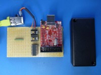
This project concerns a compact unit that offers easy one-button testing of common home & office networks, with clear red-amber-green indication of the network status, and any faults. The design is really simple, just a microcontroller, Ethernet interface, pushbutton and LEDs. The photograph shows the breadboard prototype, using a microcontroller breakout board. There are several unused components; an optimised PCB design would easily fit into a small housing.
Aside from the usefulness of the network tester, the design offers a groundbreaking feature: an Ethernet interface that does not use an Ethernet controller. This has various advantages: Simpler hardware design
- Much lower power consumption
- No complex device-drivers
- More educational: not a ‘black-box’ design.
Rather than using a standard controller & software, without no comprehension of how the internals work, the design is very open, promoting a detailed understanding of the communications mechanisms at the heart of Ethernet and TCP/IP networking.
2. Network tester
The unit provides a simple means of testing a home or office network for Internet connectivity, specifically:
- Low-level: is the cable connected?
- Medium-level: is there connectivity to an Internet gateway?
- High-level: is there connectivity to the Internet?
The three stages are shown with 3 LEDs. The user presses a single button, and if the LEDs show red, yellow then green, then the network is functioning correctly. In the event of a fault, there is a simple indication of where the fault might lie.
The 3-LED indication is ideal for use by network novices, who don't need to understand the inner workings; if the green LED is on, all is well. Network professionals may also find it a useful, a low-cost alternative to an expensive network analyser, with much greater functionality than a cheap cable tester.
3. Hardware
The design is sufficiently simple that it could be prototyped with a microcontroller breakout board, as shown above. Some notable points:
- The breakout board has a USB connection that is not required for this design, however a more advanced version of the tester might use USB for configuration & logging, so it would be worthwhile making provision for USB, but not fitting it in the first instance.
- The component count is low; Atmel SAM7 microcontroller, 3 surface mount interface ICs, and an Ethernet connector with magnetics. No voltage regulator is required, the design can run directly off a 3.2V battery supply. The design could fit into a plastic case such as shown above, the main bulk being the batteries.
- The components are readily available from catalogue suppliers at modest cost; the component cost should be around £10, in relatively small volumes.
- Surface-mount assembly will be required; soldering the microcontroller will be outside the capability of most amateur (and many professional) builders, but can easily be done by any contract manufacturer.
4. Software
Despite the simplicity of the unit, there is a significant amount of software:
- Low-level Ethernet interface
- Higher-level TCP/IP functions
- User interface (button and LEDs)
There is no operating system, real-time kernel or third-party TCP/IP stack; all the software is custom-written, or adapted from the author’s ‘TCP/IP Lean’ code, see below for details.
The software is written in C, using the IAR EWARM development environment. The code is sufficiently small that the free ‘kickstart’ edition can be used; the code will also be adapted for use with the GNU toolset when time permits. The software will be released under an open-source license, the details of this have yet to be finalised.
Want to build a project?
Bring your design to life with the Elektor PCB Service, powered by Eurocircuits. Upload the project files and order professionally manufactured PCBs or assembled boards through a proven European production platform.
Supporting KiCad, Eagle, Gerber, and ODB++ formats, the service is suitable for everything from prototypes and validation builds to series production and volume manufacturing.
Made in Europe. Fast. Reliable. Professional.
Discussion (2 comments)