
Intelligent Cuelight System for Theatres and Event Venues [130321]
The project is a complete cuelight system for theatres and other event venues. It comprises a modular channel board utilising a bus system for control and a simple remote board for each out-station. The channel board will accept signals from "Standby" and "Go" buttons and a "Ready" button on the remote out-station.
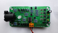
The project is a complete cuelight system for theatres and other event venues. It comprises a modular channel board utilising a bus system for control and a simple remote board for each out-station. The channel board will accept signals from "Standby" and "Go" buttons and a "Ready" button on the remote out-station. It provides a bipolar constant current output for driving local and remote signal bi-colour LEDs connected in reverse parallel. The supply source for the remote out-station "Ready" button is taken from the LED drive so the button will always be active. The installed system works over standard twin screened audio tie-lines provided that the screen is floating and not connected to ground at any point. This should be standard practice in all theatre and event venue installations. The channel board is controlled by a PIC12F615. Provision is made for a clear button. If this is fitted the "GO" LED will remain lit until the clear button is pressed.
In addition to the standard flashing red, steady red and steady green of conventional cue light systems, the intelligent version has a reverse signalling capability. If the remote acknowledge button is pressed whilst the LEDs are either off or steady red they flash alternately until the button is released again. Then they will return to the previous state.
The code has been written in MPASM assembler and the full source will be available for users to modify if they wish.
The LEDs are driven by constant current sources giving flexibility over the power supply voltage. If only one LED is fitted in the controller and one in the remote box the power supply could be a little as 9VDC. More LEDs would require a higher supply and the system will accept voltages up to 36VDC.
ELEKTOR.LABS does not support the upload of PDF files so the schematics, component placements and parts lists can be found in ZIP files under the PCB heading. You need to be logged in to download these files.
Want to build a project?
Bring your design to life with the Elektor PCB Service, powered by Eurocircuits. Upload the project files and order professionally manufactured PCBs or assembled boards through a proven European production platform.
Supporting KiCad, Eagle, Gerber, and ODB++ formats, the service is suitable for everything from prototypes and validation builds to series production and volume manufacturing.
Made in Europe. Fast. Reliable. Professional.
Discussion (3 comments)