
Microphone Preamplifier with Phantom Power
Easy to implement, the THAT1510 offers quality sound
The adventure of microphone preamps began for me at the beginning of the 80s. At first, it was with classic BC547 & cie style transistors. One day while reading "Audio hanbook by National Semiconductors", I discovered the LM387, LM381, LF357. In the early 90s, PMI launched the SSM2017. The quality was really there (good dynamics, good signal to noise ratio) The SSM2017 was then taken over by Analog Devices. For its part, Burr Brown by Texas Instrument is releasing a replacement for the INA217. Subsequently DBX Thatcorp, which only made VCA, embarked on the adventure of replacing this DIP 8 circuit with the famous THAT1510.
My mic pre follows the same template that I applied to a previous project:
https://www.elektormagazine.fr/labs/line-receive-with-rfi-and-dc-protect
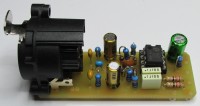
Same dimension and layout of the PCB. In this way, MIC & LINE can be juxtaposed for power bus distribution (+/-). As a result, there is only one step to building a true mic/line preamp.
I have already implemented this famous THAT1510, but the particularity of this latest version is the addition of the phantom power supply which is very useful with the podcast trend which is bringing out a new range of condenser and electret microphones requiring 48V.
I recommend that you read the AES report attached in the files (other), you will have another view of the dangers of 48V. Thatcorp offers a variety of mic preamp input protection solutions.
My point of view, when you see that many electret mics have 5V6 or 6V2 internal zeners, why power them with 48V? 12V may be suitable. And then, most field mixers also worked in 12V for audio and Phantom power. Of course U87s from Neuman & other Schoeps & cie, their internal zeners are close to 30V, there is no doubt for the 48V
Another desire to place the Phantom power supply on the PCB is to reduce the wiring and on the other hand P48 external units are not always of high quality. We do worse than better and the result, we end up with a bad signal / noise ratio.
Especially, I have not always had good echoes of commercial external phantom power. Adding noise by restricted electronics is not desirable at the source
For the schematic:
The microphone is connected to a Neutrik chassis NC3FAH2 base.
C1, C2, C3 constitute an RFI filter
R1 & R2 of 6k8 1% distribute 48V for statics
C4 & C5 block 48V to protect THAT1510. The reference is: UFW1J220MDD from Nichicon audio series. 22µF 63V is better than 50V because critical for 48V too tight. In addition, they take up little space.
R3 & R4 are recommended by the manufacturer for different ways of protecting ignition overvoltages. (see data sheet)
DZ1>4 protect the E- & E+ inputs of THAT1510
R5 & R6 are Pull Downs and balance entry symmetry. You can set values from 1k to 10k 1%
C6 remove any residual interference
C7 & C8 are decoupling capacitors
R7 & R8 supply ± the circuit
C9 is the output link capacitor
R9 is a pull down resistor
The gain is calculated with the following formula:
20 log 1 + (10 K / RG) or 6 to 60 dB
Adjusting the gain with a 10K reverse LOG potentiometer is good, but we still notice a less precise adjustment at the end of the course.
I much prefer the version with a 12-position switch in 5 dB jumps and for fine tuning, follow a gain compensator of +/- 5 to 6 dB.
Want to build a project?
Bring your design to life with the Elektor PCB Service, powered by Eurocircuits. Upload the project files and order professionally manufactured PCBs or assembled boards through a proven European production platform.
Supporting KiCad, Eagle, Gerber, and ODB++ formats, the service is suitable for everything from prototypes and validation builds to series production and volume manufacturing.
Made in Europe. Fast. Reliable. Professional.
Updates from the author