DIY Ram-Tester checks vintage 16- and 20-pin DRAMs used in TI-99/4A, C64, Amiga, Atari and others. Fast tests, OLED display, upgradable firmware.
The retro-computing scene has a new bench tool worth noting: an open-source DIY RAM tester. The Ram-Tester project by tops4u provides a fast and modern way to validate classic DRAM chips from the 1980s and early 90s. It works with many of the RAM types used in machines such as the TI-99/4A, Commodore C64/128, Amiga, Atari, ZX Spectrum, BBC Micro, and others — ideal for anyone restoring vintage hardware or repairing boards with failing memory.
What the Ram-Tester Does
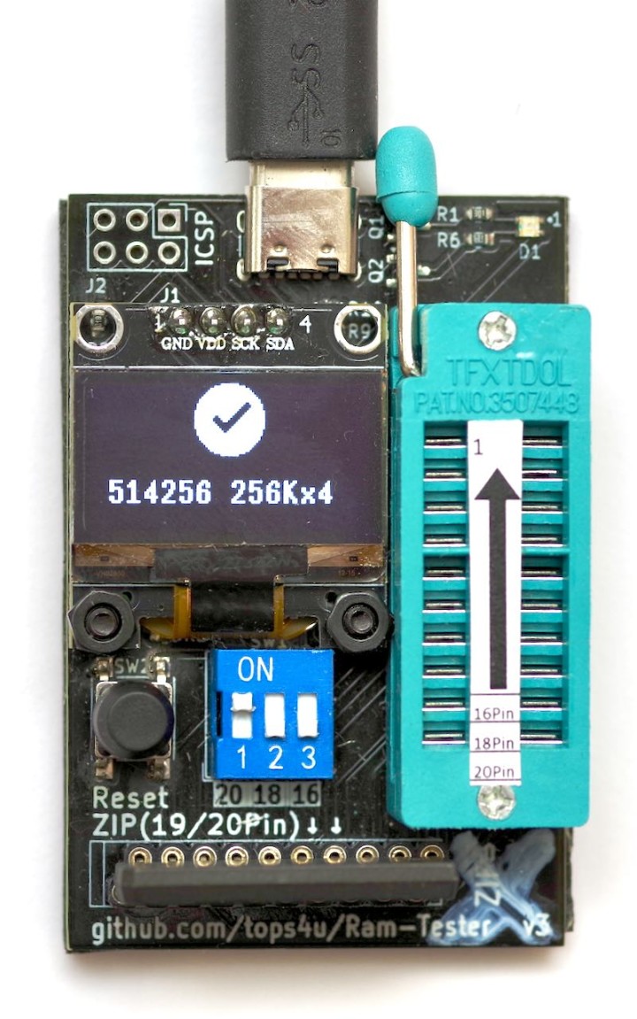
The unit tests typical 1-bit or 4-bit DRAM ICs, using either a DIP socket or ZIP adapter, and identifies faults in seconds. Output can be displayed via a small OLED screen or simpler LED status indicators, depending on how minimal a build you prefer.
tops4u’s open-source Ram-Tester. Note the URL at the bottom. Source: tops4u.
Tests cover:
Shorts to ground or VCC.
Address/decoder errors.
Stuck bits and pattern faults.
Crosstalk.
Retention and random-pattern reliability.
Typical test time is 2–4 seconds on small DRAMs (4116/4416) and around 6–16 seconds on larger chips such as 41256 or 514400. In tops4u’s video demonstration, even larger 1M×1 devices were handled — slower due to pinout limitations, but still supported.
Ram-Tester Firmware, Versions & Upgrades
Firmware is open source and updateable through an ICSP header. New RAM types are added over time; flashing newer firmware extends compatibility without replacing hardware.
The author’s current build in the video is v3.0.1, confirming active development. Selecting an illegal DIP combination displays the firmware version on the OLED screen.
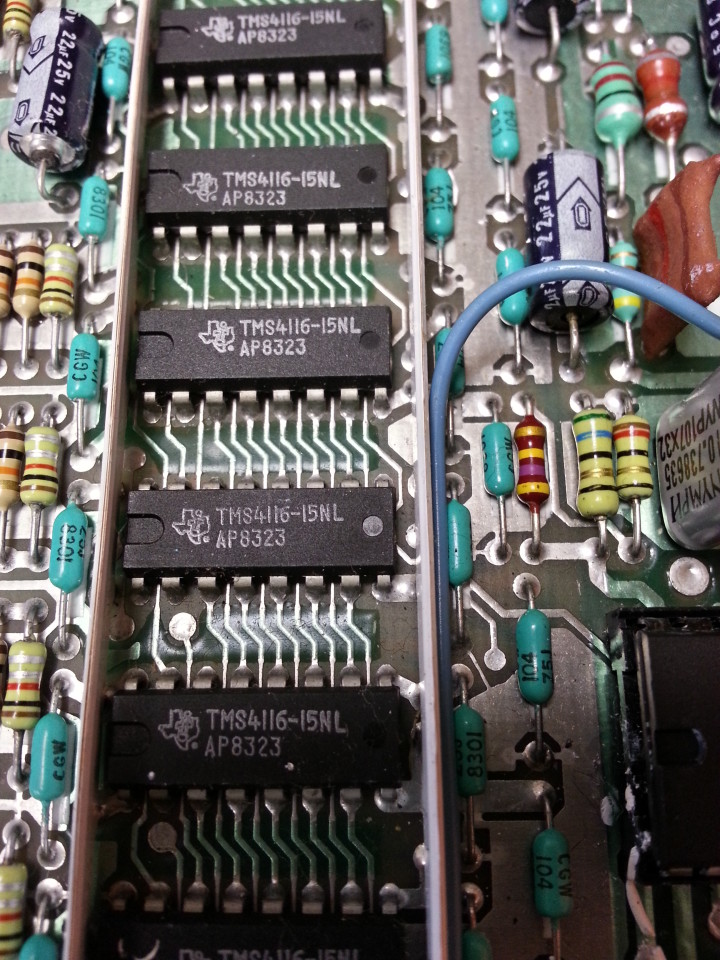
Expansion: 4116 & Multi-Voltage RAM
Older 4116-type DRAM (such as that used in my Texas Instruments TI-99/4A’s video RAM) requires additional rails (+12 V and -5 V) which standard testers don’t supply.
The video RAM chips used in my TI-99/4A are 16-pin and require a very onerous 5 V, 12 V, and -5 V.
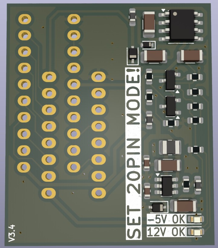
To solve this, a daughterboard prototype — shown in the video — generates the required voltages, allowing safe 4116 testing. A 4116 adapter board was designed, which works with the latest firmware. Documentation is already available for those who want to build it themselves.
The 4116 adapter board handles those voltage annoyances. Source: tops4u.
Open Source & Availability
All schematics, PCB files and firmware are public on GitHub, including both SMD and through-hole builds. Kits can be ordered commercially, or constructed DIY — just check out the readme for links.
Subscribe
Tag alert: Subscribe to the tag retro computing and you will receive an e-mail as soon as a new item about it is published on our website!
Read full article
Hide full article
About Brian Tristam Williams
Brian Tristam Williams is a content creator who’s had a passion for computers and electronics since he got a “microcomputer” at age 10. He bought his first Elektor Magazine at 16, and has been orbiting the electronics and computers ecosystem since. He first co... >>
Elektor Magazine has been one of the leading sources of information on electronics for engineers, designers, start-ups and companies for 65 years. Our magazine is powered by an active community of electronics engineers – from students to professionals – who are passionate about designing and sharing innovative ideas.
For them, we publish hundreds of items a year, in formats such as articles, videos, webinars, and other learning formats. Our mission is to share knowledge in every possible way and inspire readers with the latest developments within the electrical engineering sector.
Thank you for your vote!
Leave further comments in the fields below.
Thank you for your vote!
If you wish to leave a comment with your rating, please first use the login below. If not, just close this window.


Discussion (5 comments)