
Platino Adjustable Bench Power Supply-130406-1
A simple Platino-based lab bench power supply for not too demanding (hobbyist) applications. Inspired by the “Lab PSU for Embedded Developers”. The inconvenience of the above design is that the MCU is just a passive display; in this new design output voltage and the maximum current is controlled by the MCU.
A simple Platino-based lab bench power supply for not too demanding (hobbyist) applications. Inspired by the “Lab PSU for Embedded Developers”. The inconvenience of the above design is that the MCU is just a passive display; in this new design output voltage and the maximum current is controlled by the MCU.
Specifications:
- DC Input: 18V / 2A
- Output (1): 3.3V, 5V / 500mA
- Output (2): 0 – 15V / 1A
- Power supply output capacity: 17.5W
- 20 X 4 LCD Display
- Standard USB and banana type connectors for outputs
- High temperature auto shutdown
Features:
- (1) Output: 5V and 3.3V selectable DC voltage output.
- Standard USB Connector for 5V/3.3V output
- (2) Output: 0V to 15V adjustable DC voltage output
- Banana type connectors for 0V to 15V adjustable DC voltage output
- Cooling Fan & Control: Auto and Manual mode
- All selection by single rotary encoder with push button
- 20 X 4 LCD Display
- Input voltage from standard 18V laptop power supply
- Temperature sensor. Temperature auto shut down.
- All outputs are short circuit protected.
- Setup mode for setting limits and other settings like Fan and Temperature
- Normal mode for using the output voltages
In most of the power supply the MCU is just a passive display and voltages are controlled by a potentiometer. Such a power supply does not have any control over the output voltage and use of MCU is limited to display only. Thinking just beyond that is to use the full power of the MCU to make the digital power supply.
This involves few more components to be added to the circuit and minimize the number of potentiometers and switches .Such a design where output voltages are digitally controlled creates some problems and complications in circuit but finally we design the circuit which does its job correctly. Thanks to Platino Board and Digital Potentiometer who solve most of the problems and also minimizes the components and space.
This unit delivers the most common outputs for lab work that is, able to supply 0V to 15V DC variable voltage output in 0.1V increment of steps with 0mA to 1000mA selectable current limit. Another output of this unit is the selectable fixed voltages 3.3V and 5V with 0mA to 500mA selectable current limit. To do the settings the display has two modes of operations, one is setup mode and another is normal mode.
Power supply is divided into two major sections one is hardware and another is software, both are responsible for stability and accuracy of selection and output s. The heart of the project is the PLATINO MCU board which contains MCU ATMega328p.
The hardware is divided into a few blocks to make it simple
- Main power input and auxiliary supply generator
- Negative reference voltage generator
- Temperature measurement section
- Fan control section
- Precision reference generator section
- Positive voltage regulator
- Auto shutdown control section
- Feedback & error correction section
- Digital potentiometer section
- Output section
We will discuss each of these sections of the circuit; the schematic name of each section is mentioned near the stage. Input voltage for the unit is standard 18V adapter of laptop or other equivalent adapter.
- Main power input and auxiliary supply generator
Input voltage is connected to circuit by connecting the voltage to K1 as mentioned in Figure1. Diode D1 protects the circuit form reverse supply. 18VDC further send input for IC3 and IC4.
IC3 (LM7805) generates the main 5V supply for the Platino board and other circuitry which operates on 5V. IC4 (LM7812) generates 12V DC supply for fan control circuit as auxiliary supply.
- Negative reference voltage generator
This section contains MAX660 (IC5) for converting +5V to -5VDC supply which is required to generate negative reference for positive voltage regulator section to start from 0V. The output for IC5 is connected to IC6 (LM337L), which is a negative voltage regulator and its output is adjusted by preset P2 to -1.27V. This -1.27V is used as negative reference for positive voltage regulator to start form 0V instead of its 1.27V.
- Temperature measurement section
Temperature is measured using the precision temperature sensors IC7 LM335. This IC requires very few supporting components and less space due to TO-92 package style. Output of IC is send to PC4 input of Platino board. MCU reads the voltage and display the reading of the temperature according to the voltage. Also the measured temperature is used to auto shutdown the power supply when the temperature reaches a high level. User can also set the shutdown level in setup mode “Threshold Temperature” configuration.
- Fan Control Section.
Fan is used to cool the unit as it is fixed in the enclosure. A 12VDC fan is used inside the enclosure and controlled by MOSFET T1 BS170 via Platino board pin PD1. Connector K5 is used to connect the fan. Connector K8 can be used as jumper to set the fan operation in manual mode by making Platino board pin PC6 “High” or “LOW”. Fan operation mode can be set in auto or manual mode by using the setup mode of power supply. In auto mode the fan is controlled by the Platino MCU via pin PC6, and it will become ON depending upon the temperature level that is,20 °C before Threshold Temperature value. For below that level fan remains OFF in auto mode. If manual mode is selected than it will check the status of K8 to ON or OFF the fan.
- Precision reference generator section
IC11 LM336 is used to generate the reference signal for the Platino MCU. The MCU takes the reference of this to do the calculations of all other voltages which are needed to measure the power supply. IC11 LM336 is precision reference generator which requires less space due to To-92 package style and also less surrounding components. Preset P1 of 10K is used to adjust the reference voltage to precise 5V with the help of voltmeter. This is one time setting for the power supply for setting the reference voltage for MCU. This reference voltage connected to AREF of Platino board.
- Positive voltage regulator
There are two outputs from the power supply and hence two separate positive voltage regulators are used. Same type of regulators is used to keep the simplicity and similarity in circuit. IC LM2576 is an adjustable step down switching regulator that is used as a positive voltage regulator on the two sections of power supply. In the first section IC1 LM2576 is used to give 0V to 15V / 1A adjustable output. IC2 LM2576 gives 3.3V/500mA and 5V/500mA selectable outputs in the other section. Both sections are digitally controlled by Platino board MCU.
0V to 15V adjustable voltage output is available on connector K6. And 3.3V/5V selectable output is available on connector K7. The output of LM2576 starts from 1.23V as per datasheet, therefore negative reference voltage is connected to IC1 LM2576 pin 3 (which is ground in) to start the output from 0V by keeping the IC1 ground at negative voltage. Input voltage for both IC1 and IC2 is 18VDC and connected to pin 1 of both IC’s after diode D1. The identical filter circuit is used as output of both IC’s with change in current rating of components like coil L1, L2 and Diode D2, D5 respectively. The values of components are so selected so that they work as per the requirements of voltage and current.
- Auto shutdown control section
Auto shutdown is used for the protection of power supply. It protects the unit from damage though short circuit, over temperature, over current. Platino board pin PB6 is used to control the IC1 LM2576 ON/OFF via MOSFET T2 BS170. As T2 is having negative voltage at source pin, diode D8 is use to avoid any negative voltage on Platino board pin PB6. Platino board pin PB7 is used to control the IC2 LM2576 ON/OFF in case of short circuit, over temperature, over current detected at its output. These sections are handle by the Platino board MCU.
- Feedback & error correction section
This section is responsible for controlling the output voltages and currents of both regulators. After the good practice, components are so selected to work as per the requirement. The main parts in this section are OPAMP and MOSFET. This section generates and controls the feedback of IC1 and IC2 with the control signal from the Platino MCU.
For IC1 PW0 is the digital potentiometer signal to control the feedback voltage. Current measurement signal is connected to the MCU via pin PC1 of Platino board and the voltage measurement signal is connected to MCU via pin PC0 of Platino board
For IC2 PW1 is the digital potentiometer signal to control the feedback voltage. Current measurement signal is connected to MCU via pin PC3 of Platino board and voltage measurement signal is connected to MCU via pin PC2 of Platino board.
The working of feedback & error correction section is as follows
Op amps IC9a and IC10a will compare the non inverting terminal voltage to inverting terminal voltage and then give the outputs according to the differences and these outputs decide the feedback impedance to the feedback pin of the regulators. In order to understand clearly consider a voltage say V (between 0-5V) at the inverting terminal of the op amp, this will drives the op amp to a very low state, so this value will be much lower than the threshold voltage of MOSFET, so the MOSFET will be in high impedance state, in order to meet the 1.23V at feedback terminal, the regulator drives the output to high but this output is again fed back to the non inverting terminal, this will again drive the output of op amp resulting in a lower impedance, thereby, the overall circuit will maintain a voltage at the non inverting terminal same as that of inverting terminal of op amp.
The current sensing section is made from OP Amp IC9b and IC10b. The current flowing through the load is converted to voltage by means of the voltage drop across the Shunt resistors R5 for IC1 and R16 for IC2. This dropped voltage is fed to the inverting terminals of OP Amp’s. This will give rise to the output of the OP Amp, result in lower impedance MOSFET, again resulting in a voltage drop at Non-inverting terminal, this will cause equilibrium between the voltages at Non-inverting and inverting terminals. So a same voltage drop as that of shunt resistor is found across the 100R resistor R9 for IC1 and R23 for IC2. So the current flows through 100R resistor proportional to that of load current, and this same current flows through 2k resistor R17 for IC1 and R11 for IC2 and gives a voltage drop proportional to that of load current, this voltage is fed to the microcontroller to read the current value. In order to protect the microcontroller terminal Zener Diode 5.1V (D3, D4, D6 and D7) has been used. The regulated output voltage (0-20V) is scaled to 0 to 5V and fed to the microcontroller.
- Digital potentiometer section:
IC8 MCP42010 is a dual digital potentiometer (50K) with SIP interference used to control the feedback voltage depending upon the digital input from MCU. POT PW0 is used for IC1 through IC9a and POT PW1 is used for IC2 through IC10a. PB3, PB4, PB5 and PD0 are SIP interface signals from the MCU to control the digital potentiometer wiper in order to change the voltage as per the correction required in outputs.
Correction 22/5/2014: due to a strange mistake an MCP4261-103E/P was used in our prototype instead of the planned MCP42010. These chips are pin compatible 10k digital potentiometers, but they are not software compatible. Unfortunately, the BOM was not updated and now the software is wrong. The current software expects an MCP4261-103E/P. We are working on creating new software that will handle the MCP42010.
- Output section:
Output from IC1 regulator is connected to the front of enclosure via banana type connectors (Black and Red) through connector K6 on PCB. Output from IC2 regulator is connected to the front of enclosure via standard USB type connector through connector K7 on PCB.
Software:
The software is written in BASCOM AVR for ATMEGA328P microcontroller. The Platino board is used for further development of the project. The software part divided into the following sections
- Display section
- Measurement section
- Control section
Display section:
Display section is build with Platino board and 20 x 4 LCD. This section of program generates a display on LCD initialized as “Platino Instrument series 1.0” and after name of the project that is “Platino Adjustable bench Power Supply”. After initializing, It display “Manu” screen with “Setup Mode” and “Normal Mode” options. Now with the help of rotary encoder with push button on Platino board we can select any option. On selected option we need to press the pushbutton of the rotary encoder to view options of the Normal or Setup mode. A long press of the same button returns back to Main Manu of display.
Setup Mode:
In this mode we can make the configuration and settings of voltage, current, Fan and Temperature by selecting its options. A long press of the same button returns back to the Main Manu of display.
Normal Mode:
In this mode the actual outputs are switched ON to be used by the user. Also we can use the rotary encoder to change the 0V to 15V output as per requirement. A long press of same button returns back to the Main Manu option of display. All outputs are available in normal mode only.
Measurement Section:
Microcontroller takes the inputs of output voltage and current feedback from Feedback & error correction section of hardware. It also measures the voltage and current with reference to reference signal on AREF pin of MCU. Temperature measurement is carried out by the software and is displayed on LCD.
Measuring signals are scaled to 0 to 5V in hardware and send to ADC of MCU.
Control section:
Depending upon ADC input value MCU generates the control signals for IC8 digital POT to control the output voltage and current. It also generates the auto shutdown signals for IC1 and IC2 depending upon current and temperature values and the limit value set in setup mode. It generates the Fan control signal as per configuration in setup mode.
In software the microcontroller reads the output voltage and increments or decrements the digital pot in order to meet the desired voltage level. It also monitors the current and limits the output voltage if the load current surpasses the current limit. If short circuit detected (Very High current) the microcontroller shutdowns the particular regulator and resets the digital pot to zero position. Also the microcontroller shutdowns the regulator, if it detects high temperature. The upper current limits and temperature limits can be programmed by the user.
Microcontroller Pins Usage Description:
- PB0 –PB2: Encoder with pushbutton.
- PB3 to PB5 with PD0 used for SPI communication between microcontroller and the digital port. The configuration given below:
- Data in = PB4
- Data out = PB3
- Chip select = PD0
- Clock = PB5
- PB7 and PB6 control the ON and OFF of regulators.
- PC0 to PC3 measures the output voltage and current of both Regulators IC1 and IC2.
- PC4 measures the Temperature.
- PC5 controls the Backlight of LCD
- PC6 controls the fan.
Jumper settings required on Platino Board:
- JP3: PC5
- JP4: PB0
- JP5: PB1
- JP6: PB2
- JP10: PB6
- JP9: PB7
- JP8: RESET
- JP11: PB7
- JP12: PB6
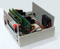
Building the Prototype:
Build the Platino with required jumper settings, LCD, Rotary encoder with pushbutton, ATMEGA328P MCU and other required components. The Add-on board of power supply is so designed to fix exactly to the back of Platino with the help of connectors. Bolpa enclosure is used to fix everything inside it which includes Platino with 20 X 4 LCD, Rotary encoder with pushbutton, PSU add-on board, 12VDC fan, Power Jack, ON/OFF switch, banana connectors, and USB connector.
Testing Prototype:
The Prototype is tested using its full capacity load
- For 0 to 15V /1A output: Connected 15 Ohm/ 30W resistor load
- For 5V/500mA output: Connected 10 Ohm/ 10W resistor load
Also take dynamic load testing at 1 KHz for 15V/1A, 10V/1A and 5V/500mA
Check for short circuit and auto shutdown test by shorting outputs to ground.
Check over current by setting the limit value, reduce the output voltage to keep set current limit .
Update 22/5/2014
Due to a strange mistake an MCP4261-103E/P was used in our prototype instead of the planned MCP42010. These chips are pin compatible 10k digital potentiometers, but they are not software compatible. Unfortunately, the BOM was not updated and now the software is wrong. The current software expects an MCP4261-103E/P. We are working on creating new software that will handle the MCP42010. New software will be posted here.
Update 25/11/2014
The software has been corrected to use the MCP42010. You can download it below. Please give it a try and very sorry for the long wait.
Want to build a project?
Bring your design to life with the Elektor PCB Service, powered by Eurocircuits. Upload the project files and order professionally manufactured PCBs or assembled boards through a proven European production platform.
Supporting KiCad, Eagle, Gerber, and ODB++ formats, the service is suitable for everything from prototypes and validation builds to series production and volume manufacturing.
Made in Europe. Fast. Reliable. Professional.
Discussion (0 comments)