
Review: The I2CDriver Tool
on
After unboxing the contents of the I2CDriver (Core) tool kit can be seen in Figure 1 – included is a circuit board with a Micro USB port and three groups of pin headers to hook up three I2C peripherals. On the underside, four rubber feet ensure that the board is raised from the bench surface and does not slide around too freely.
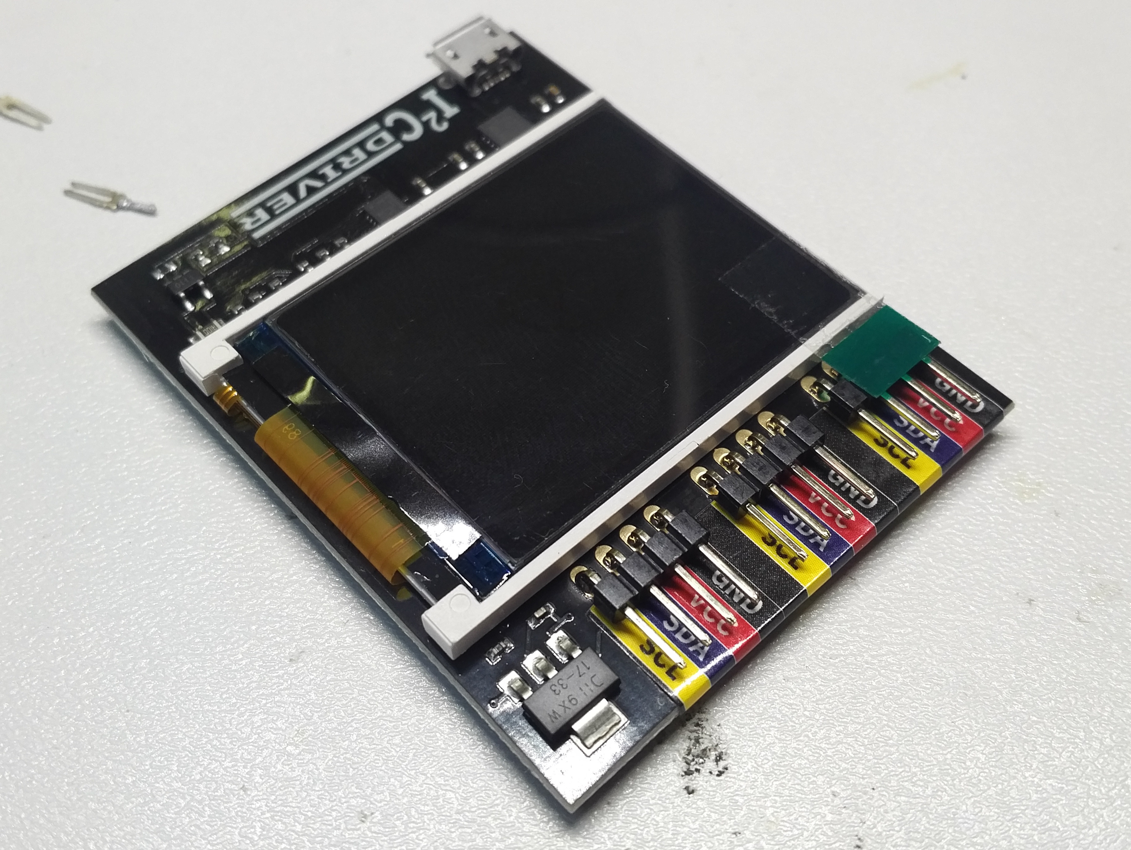
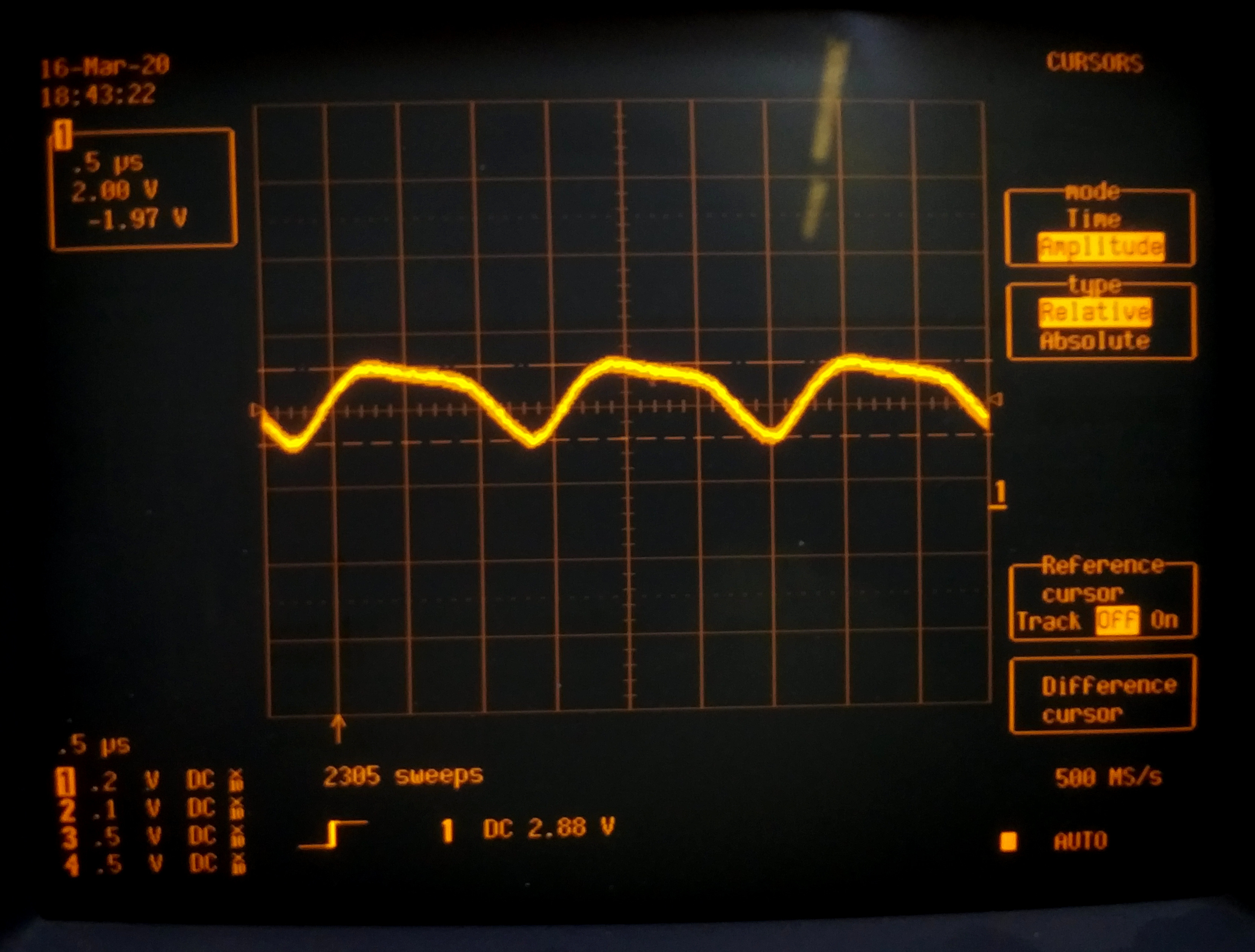
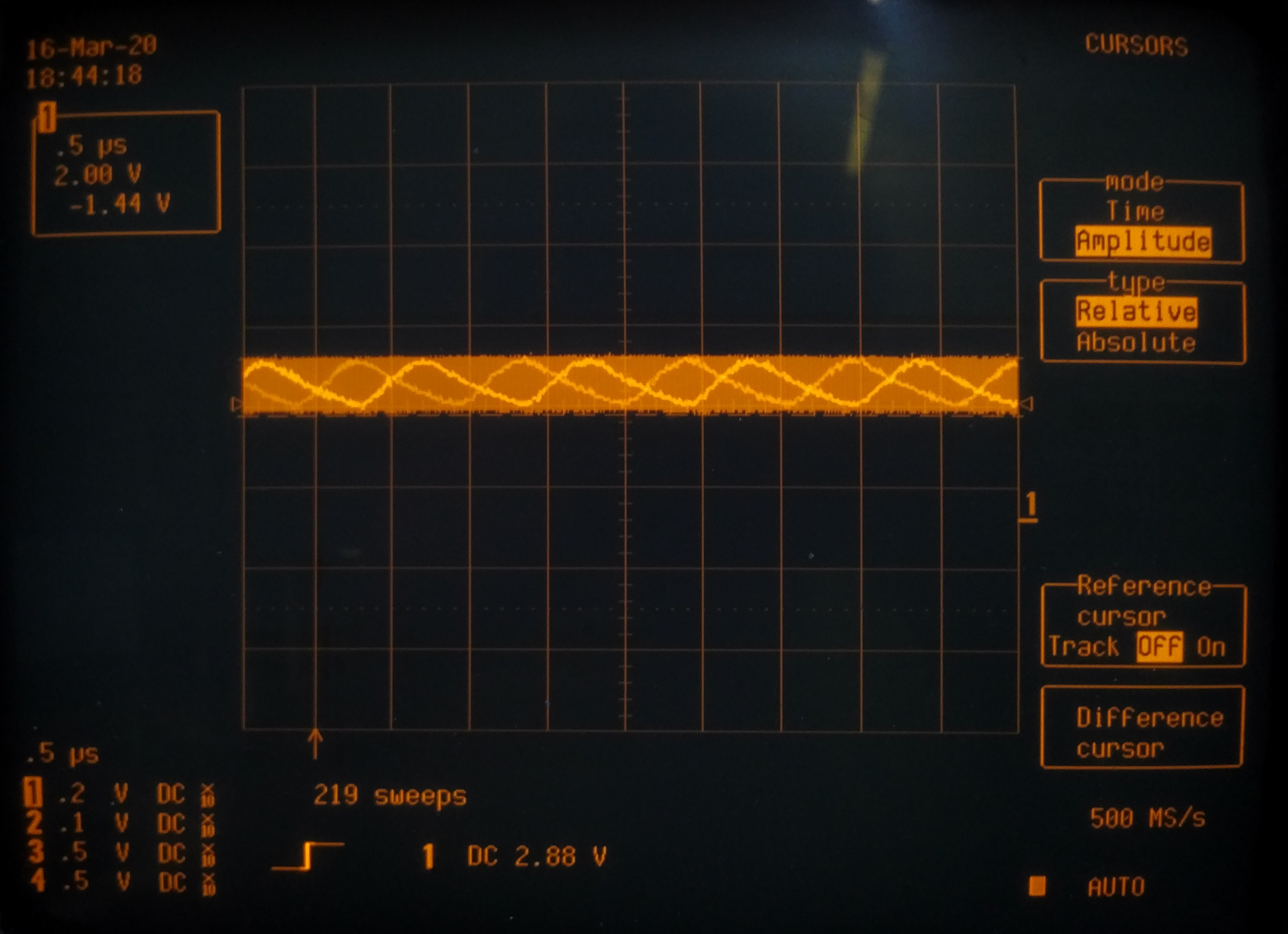
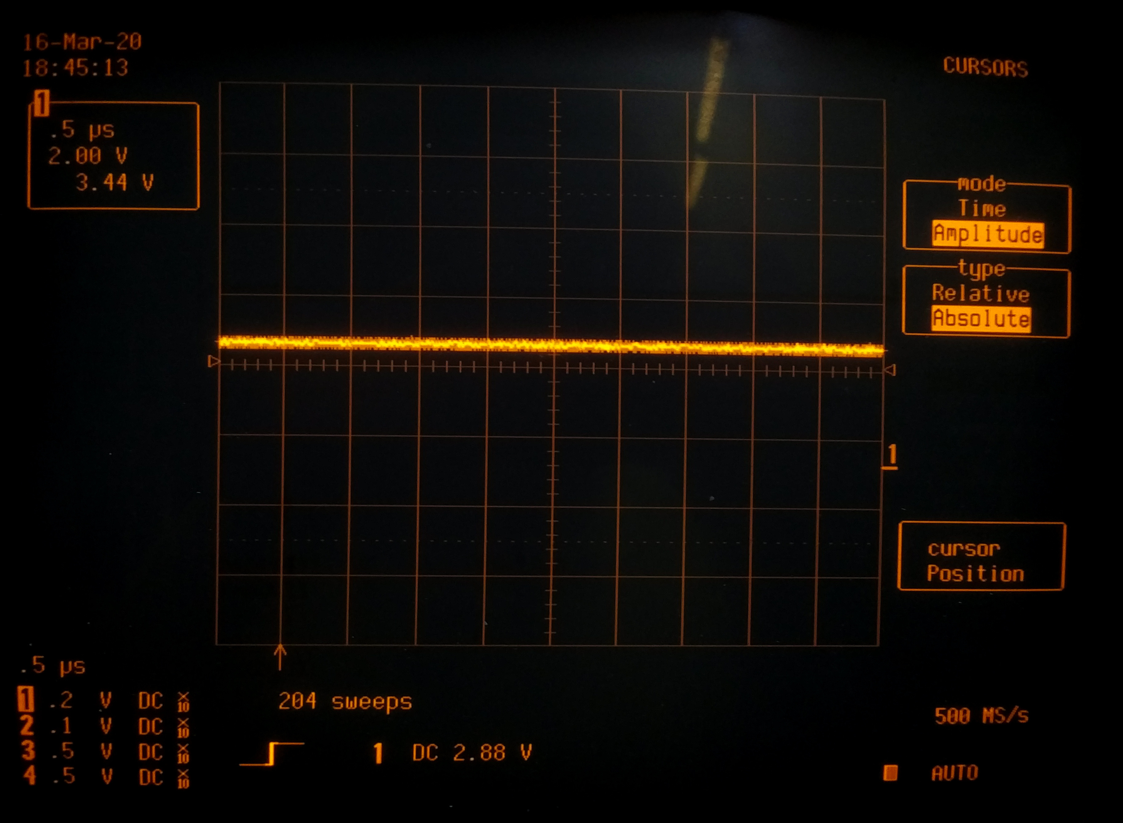
For the I2CDriver Core Kit, Excamera Labs includes three 100 mm-long cables terminated in Dupont-type female headers to provide the I2C signals to the peripheral devices. The voltage regulator on board the I²CDriver can deliver a total of 470 mA maximum output current at 3.3 V to power three I2C peripherals and signals are 5V tolerant. The board features an 8-bit microcontroller from the Silicon Labs EFM8 Laser Bee family of devices. The waveforms shown in Figures 2, 3 and 4 indicate the ripple level you can expect on this 3.3 V supply rail at various levels of peripheral loading. There is DC continuity between the PC USB port and peripheral devices, i.e. no galvanic isolation.
Hook up some hardware
The author has recently been working on the ‘HygroSage’ humidity sensor which uses an I2C bus for communication with a processor. This seemed like a good opportunity to simply insert the I2CDriver between the PC and the sensor (see Figure 5). This sensor’s has relatively low power requirements so we can power it directly from the PC via the I2CDriver board.
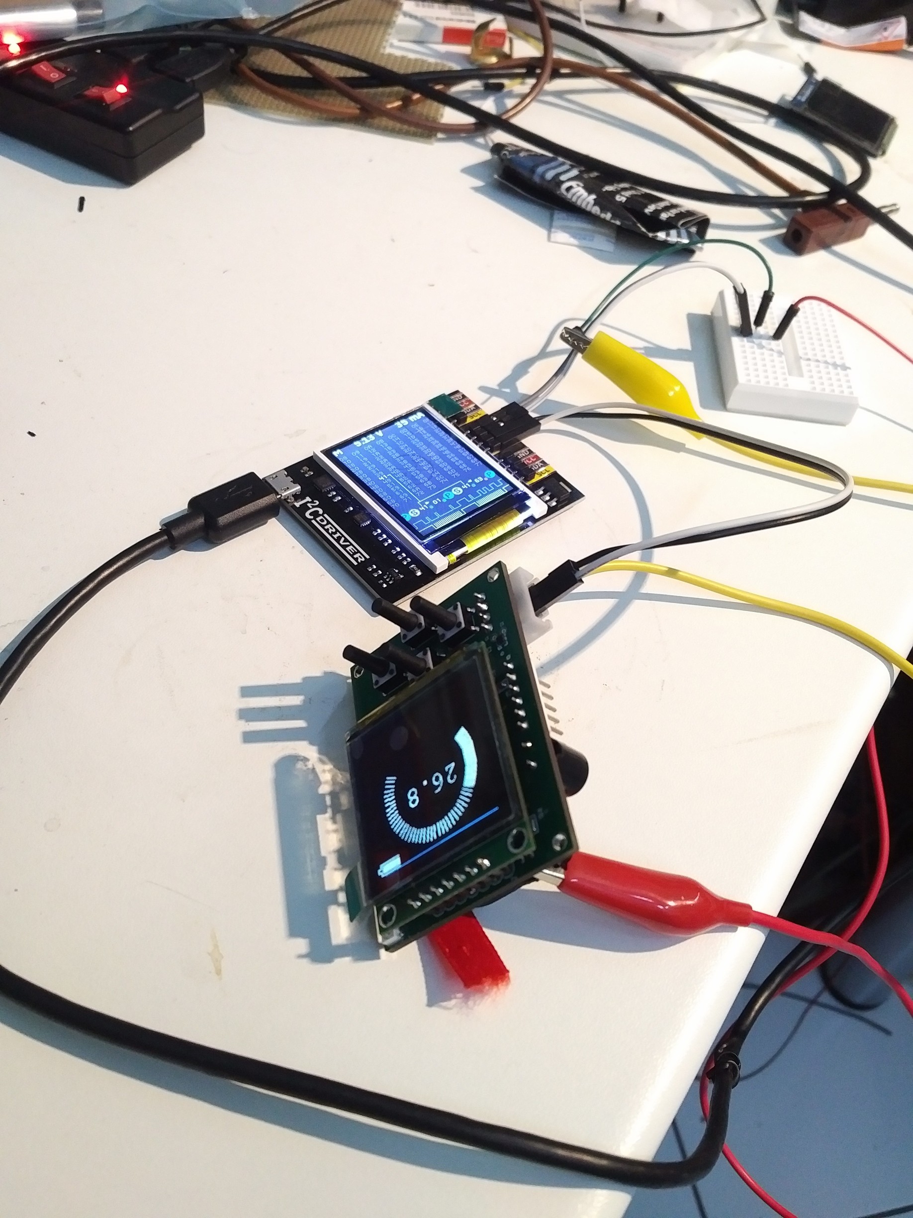
The HygroSage unit started without any problems and its current consumption is shown along the top line of the I2CDriver screen. The I2CDriver display shows a grid of all the nodes but communication activity with any of the nodes is only shown once the software is installed and running on the PC. This software is described in more detail in the next section, it was noted that the software sometimes did not boot up correctly. In the case of a successful start, the display showing a grid of all the node numbers and the volume of traffic passing through each node indicated by the colour of the node. This forms a sort of ‘heatmap’ Figure 6 of all active network nodes. In any I²C network with multiple devices, you will be able to see at a glance which ones are the most active.
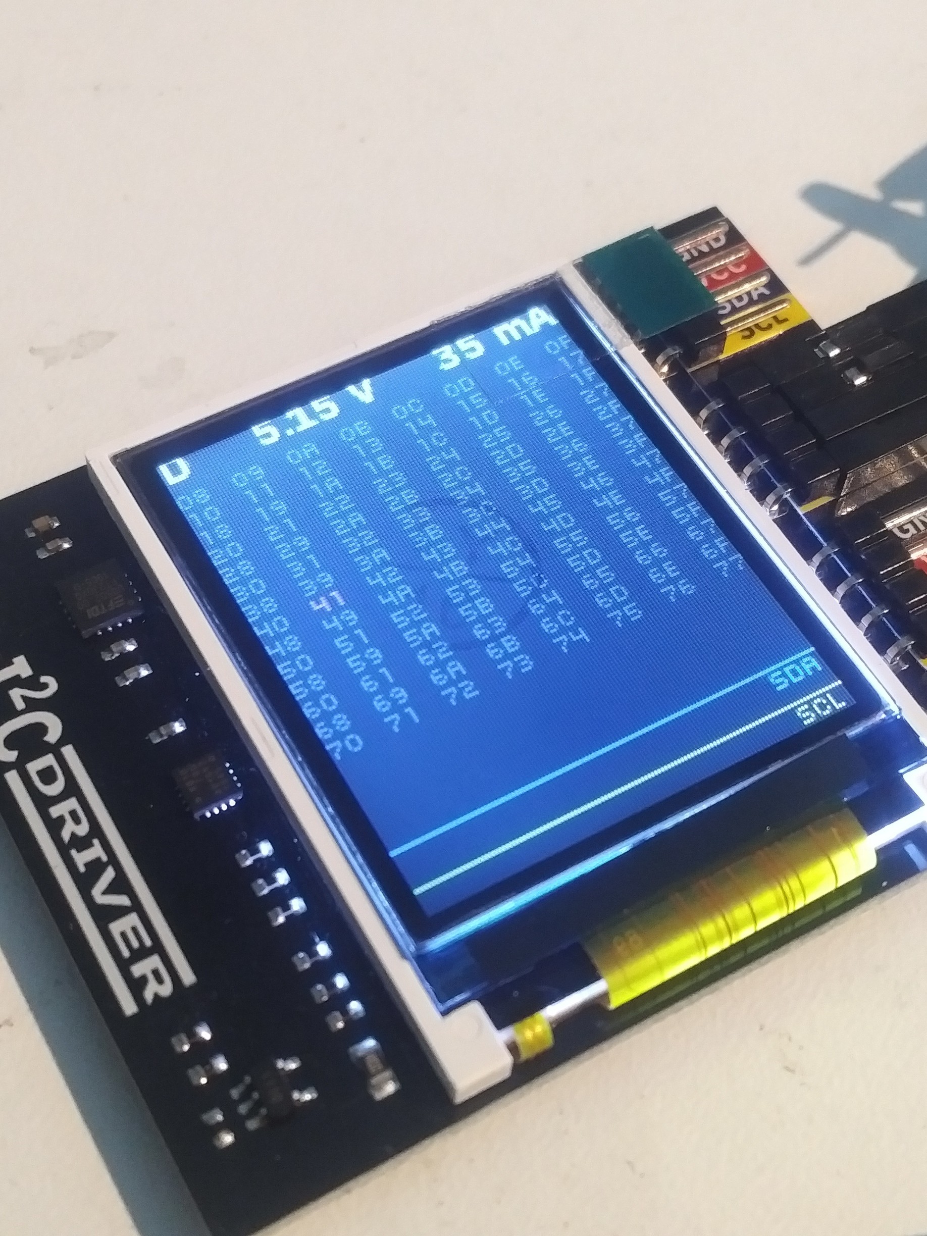
The colour display has quite a narrow viewing angle so that the screen information such as differences in the ‘heatmap’ shading are barely visible from certain angles.
Installation
Here you will find the i2cdriver-installer.exe file under the Resources tab which will install the Windows software.
After the download, you have to click on it on the right and mark it in the settings dialogue as coming from the local computer before the operating system allows the installer to be processed. Developers working with Linux or Mac OS can also find the necessary setup instructions on the above website.
After the installation is finished in Windows we open the folder C:\Program Files (x86)\Excamera Labs\I2CDriver, where there will be both a command-line and a GUI version of the product
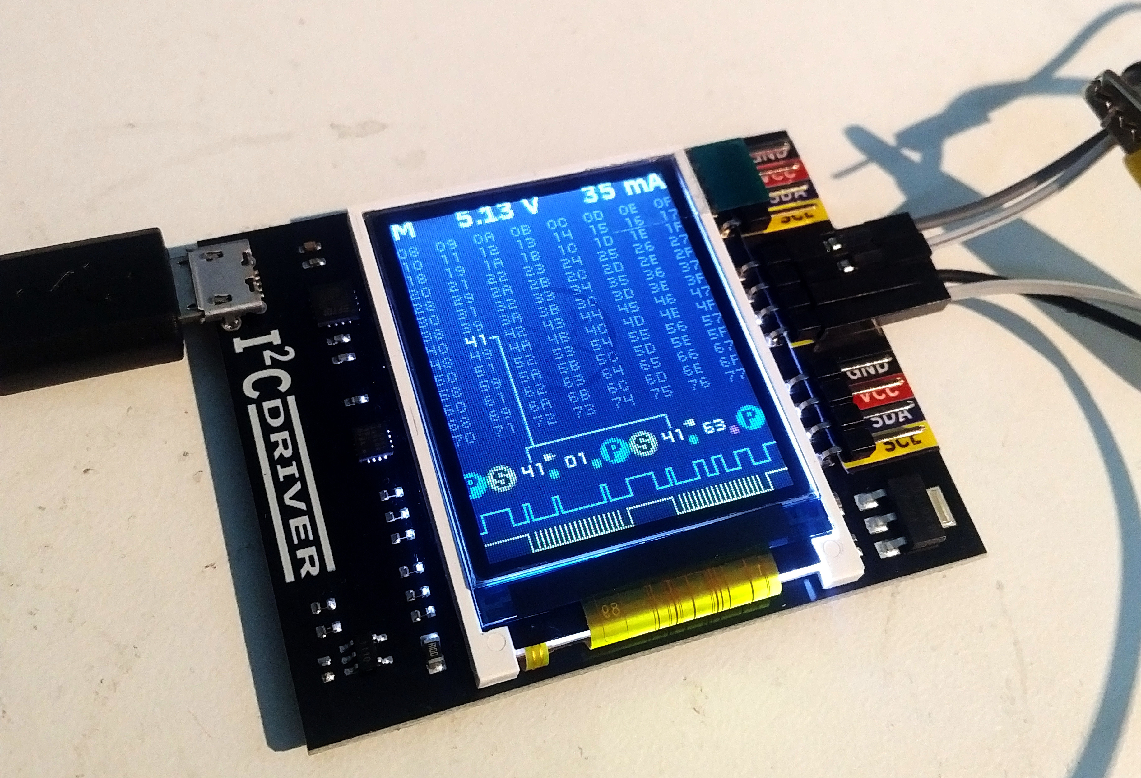
If you start the software with a connected I2CDriver and select Monitor Mode you will be able to see the last communication transaction as shown in Figure 7.
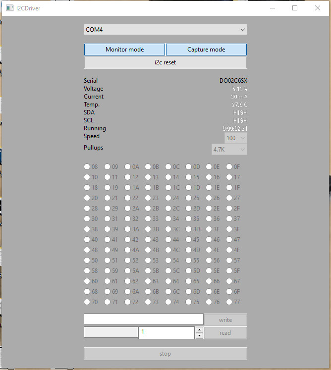
In practice, however, the use of the analysis function is limited, because in almost all cases more than one packet of information is passed at any one time. In this case, select Capture Mode instead. The button then appears activated, as shown in Figure 8.
The Capture function was tested by invoking a system error and then viewing the captured communication exchanges. Events leading up to an intermittent system failure can thereby be captured and examined in much the same way that hardware signals leading up to such an event can be recorded on a digital storage scope.
Hardware Interaction
Some time ago the author was required to implement a relatively complex algorithm on a controller. The most convenient way turned out to be to initially get the procedure running on a PC and then port it to the controller.
A similar procedure can be used when working with more complex sensors in an embedded environment. In the command prompt, i2ccl is a program that you can use to send commands to the I2CDriver using the following example:
C:\Program Files (x86)\Excamera Labs\I2CDriver>i2ccl.exe
Usage: i2ccl <PORTNAME> <commands>
Of particular interest here is the ability to write or read information in individual registers of connected devices. This not only helps when working with novel sensors, but can also be used to read out information during (automated) test runs.
If you don't want to program in the shell, you can rely on a Python API. The manufacturer demonstrates the use of a group of ready-made sample drivers - the following snippet can be used to collect information from an LM75B digital temperature sensor:
import i2cdriver
i2c = i2cdriver.I2CDriver("/dev/ttyUSB0")
d=i2cdriver.EDS.Temp(i2c)
d.read()
17.875
d.read()
18.0
The actual control API is simple and is available to view at GitHub:
class LM75B:
def __init__(self, i2, a = 0x48):
self.i2 = i2
self.a = a
Excamera Labs implements the hardware drivers using the Python OOP API. In this snippet self is a driver required by the language specification, while i2 is an I2C- driver object. Finally, a defines the address at which the sensor can be accessed.
Information held in the register can then be read in using the following commands:
def reg(self, r):
return self.i2.regrd(self.a, r, ">h")
def read(self):
return (self.reg(0) >> 5) * 0.125
It should be noted that the Scan-command used in i2cdetect is called from the Python command line and performs the scan function known from OrangePi and Co.
Finally, reference is made to the documentation available here. It explains both the I2C-API and the physical communication protocol — if you are already familiar with the FTDI-API you can also address the I2CDriver directly.
Conclusion
For anyone developing applications that rely on I2C bus protocols the I2CDriver tool can provide a whole raft of data to help identify and diagnose any system problems. Regardless of whether it is a quick analysis of the activity of an I2C network or the integration of a new sensor — the board provides valuable help.
The price is reasonable considering the time saved and convenience it brings to speed up hardware development. It has the ability to quickly capture and store information that would otherwise require the setup of a whole range of sophisticated test equipment. If it could also be used in stand-alone mode it would undoubtedly extend the usefulness of this device further.
Want more great Elektor content like this?
Then take out an Elektor membership today and never miss an article, project, or tutorial.
Discussion (0 comments)