
Simple Dual Voltage Bench Power Supply
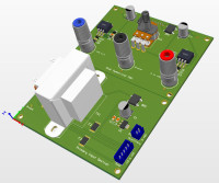
This compact dual power supply is intended for general use on an electronic workbench. It has few distinguishing features apart from being easy to make, compact and is constructed from readily available SMD components. The circuit design is taken from manufacturer’s application notes with minor embellishments. It has been designed to have outputs of 0 to +/- 15 volts (dual tracking) with a nominal output current of 250mA.
In addition to the circuit diagram, I have produced a detailed BOM, PCB design and all of the Gerber files required to order the components and build this circuit. To simplify the final assembly, and to produce a compact design, the Potentiometer and power output sockets have been employed to mount the PCB on the front panel. Please see the full description in 'Dual Bench Power Supply.pdf'' in the 'OTHER' Section.
Build This Project
Bring this design to life with the Elektor PCB Service, powered by Eurocircuits. Upload the project files and order professionally manufactured PCBs or assembled boards through a proven European production platform.
Supporting KiCad, Eagle, Gerber, and ODB++ formats, the service is suitable for everything from prototypes and validation builds to series production and volume manufacturing.
Made in Europe. Fast. Reliable. Professional.
Discussion (3 comments)