A simple voltage-controlled oscillator (VCO) built with just one operational amplifier and a few passive components.
It is instructive, easy and even fun to play around with the free circuit simulator LTSpice every once in a while. Here we show you how to analyse and understand a simple opamp-based square wave oscillator taken from an “old” datasheet before changing it into a voltage-controlled oscillator.
Building the circuit on a breadboard shows that it really works. The simulations are available for download below to get your own experiments up and running quickly.
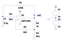
We start with a circuit from the Texas Instruments’ datasheet for the TL082. The circuit is a simple square wave oscillator with an output frequency of around 0.5 Hz. The output frequency is determined by two parameters:
The time constant set by R1 and C1, which is 100 kΩ * 3.3 µF = 330 ms.
The comparator switching levels set at 90% of the output voltage.
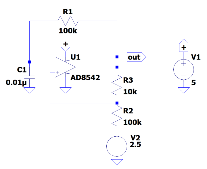
For experimenting purposes I changed the circuit a bit into a single-supply circuit oscillating at about 170Hz.
C1 = 10 nF
R2 = 100 kΩ
R3 = 10 kΩ
U1 = AD8542
Removed balancing resistors R4 and R5
C1 is not connected to half the supply voltage as that isn’t necessary (try for yourself in LTSpice or on a breadboard). For R2 however, this is obligatory as we want the voltage on the non-inverting input to swing around 2.5 V.
The time constant R1-C1 has become 100 kΩ * 10 nF = 1 ms.
The comparator switching levels that are now set at 91% of the output voltage.
Simplified schematic with an AD8542 (included in LTSpice) to make it run from a single supply.
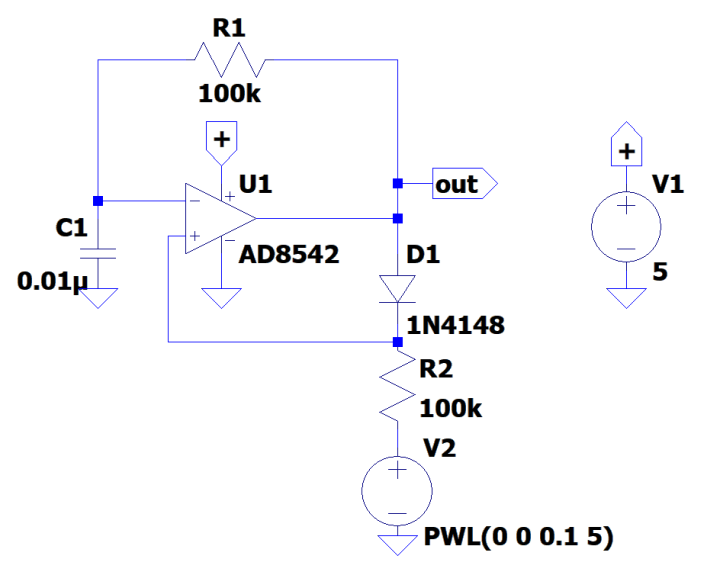
How can we change this into something that can be controlled by a voltage? As it seems difficult to turn the time constant R1-C1 into a voltage-controlled time constant, using the comparator switching levels instead may be a better option. Since these are already voltages, it will be easier to influence them.
Adding or subtracting a constant voltage from the non-inverting input makes no sense as it will simply shift both switching levels. What we want is to change the distance between the two levels. Changing the value of R2 would do this.
R2 is connected to a constant voltage source of 2.5 V; if we could make it variable, then we are already half-way. Changing this voltage will shift both levels up or down, so how can we change the circuit to make it shift only one of the two levels?
With a diode!
If we replace R3 by a diode, then, when the output of the op-amp is high, the diode will pull the non-inverting input up, because its impedance is much lower than that of R2. But when the output is low, the diode will block and the voltage on the non-inverting input is only determined by the source connected through R2.
With this trick, the upper switching level is fixed, but the lower switching level has become voltage controllable. We can now control the distance between the comparator switching levels and therefore control the oscillator’s frequency.
Thanks to diode D1, V2 can now control the frequency of the output signal.
There is, of course, a downside, which is that the duty-cycle of the output signal is now no longer a constant 50%, but changes with the frequency. It will be close to 50% when the control voltage is close to zero and will increase to 100% when the control voltage increases. Oscillation will stop when the lower switching level comes too close to the upper switching level and the op-amp can’t handle it anymore. The simulation shows this nicely.
Attached below is an Excel sheet with frequency and duty cycle plots. The minimum frequency was 175 Hz and the maximum frequency was over 3 kHz, which is more than four octaves. The duty cycle ran from about 38% up to 93%.
Build This Project
Bring this design to life with the Elektor PCB Service, powered by Eurocircuits. Upload the project files and order professionally manufactured PCBs or assembled boards through a proven European production platform.
Supporting KiCad, Eagle, Gerber, and ODB++ formats, the service is suitable for everything from prototypes and validation builds to series production and volume manufacturing.
Elektor Magazine has been one of the leading sources of information on electronics for engineers, designers, start-ups and companies for 65 years. Our magazine is powered by an active community of electronics engineers – from students to professionals – who are passionate about designing and sharing innovative ideas.
For them, we publish hundreds of items a year, in formats such as articles, videos, webinars, and other learning formats. Our mission is to share knowledge in every possible way and inspire readers with the latest developments within the electrical engineering sector.
Thank you for your vote!
Leave further comments in the fields below.
Thank you for your vote!
If you wish to leave a comment with your rating, please first use the login below. If not, just close this window.

Discussion (1 comment)